At a glance
| Patent number | CN215294199U (application CN202120369581) |
| Type | China utility model (实用新型) - protects product shape and structure |
| Original title | A kind of manual disassembly and quick connection device for camera equipment and camera equipment (一种用于摄像器材的手动拆卸快速连接装置及摄像器材) |
| Patent owner | Dongguan Zhipin Creation Digital Technology Co ltd |
| Inventors | Chen Hongtao |
| Filing date | 2021-02-10 |
| Grant date | 2021-12-24 |
| Status (China) | In force in China until at most 2031-02-10 (if annual fees are paid) |
| Patent family | Chinese filings only - no US, European, Japanese, PCT or other filings listed |
| Cited by | 14 later documents |
| Source | Google Patents (search for CN215294199U) |
What the claims cover, in plain language
Claim 1 - A manual quick connection device for camera equipment comprising a locking device and a detachable connecting piece. The locking device includes a fixed seat, a driving member rotatably connected inside it, and a locking member inside the driving member. The driving member’s inner wall has a communicating first groove and second groove, with a limiting part at the upper end of the first groove. The locking member has a first elastic piece and a positioning piece resting on it. The connecting piece has a limit protrusion on its side wall. When the driving member rotates to the locking position, the protrusion is clamped by the limiting part in the first groove. When rotated to the release position, the positioning piece wedges between the fixed seat and driving member, leaving the protrusion free to move in the second groove. A locking spring is arranged circumferentially between the driving member and the fixed seat.
Claim 2 - The fixed seat’s bottom has circumferentially spaced sliding grooves and through slots, with a stop part at one end of the sliding groove. The driving member’s outer wall has a radially extending sliding block and toggle block riding in these slots. The locking spring’s ends abut the stop part and the sliding block. Claim 3 - A button device with a button is on the outer periphery of the toggle block, contacting it. Claim 4 - The button device includes a casing and a second elastic piece located between the button and the casing. Claim 5 - The limiting part has an upwardly inclined first limiting slope extending from the first groove to the second groove, and the limit protrusion has a matching second limiting slope. Claim 6 onward - The fixed seat has at least one protruding block near the connecting piece, engaging a positioning slot on the connecting piece.
This is a simplified reading for orientation only. The legal scope is defined by the exact claim wording in the official Chinese document.
What this means for US production
This patent was filed only in China and is currently in force in China until at most 2031-02-10 (if annual fees are paid). Because there is no US or other foreign counterpart, the specific design described here is not restricted by this particular patent in the United States. However, making or selling this exact product in China needs the owner’s permission.
Two points to settle early:
- Other patents may exist. The camera quick-release plate field is heavily patented globally. Companies such as Shenzhen Leqi Network Technology Co., Ltd. (holding WO2024119929A1 and WO2025039673A1), Videndum Media Solutions S.P.A. (holding WO2025172973A1), and Shenzhen Ousenlong Kechuang Co., Ltd. (holding WO2026123145A1) have filed later international applications citing this patent, indicating active intellectual property development in this space. We strongly recommend a freedom-to-operate (FTO) review before launching a product based on this mechanism in the US or elsewhere.
- Load-bearing verification. The patent describes the mechanical interaction but does not specify maximum payload capacities. The dimensions, material grades, and spring forces must be set in design and confirmed on prototypes to ensure they safely support intended camera weights.
Customization and manufacturing
What can be customized
| Area | Options |
|---|---|
| Dimensions | Overall diameter and height to match standard plate footprints (e.g., Arca-type or proprietary sizes) |
| Materials | Aluminum alloy, stainless steel, or reinforced polymer for the fixed seat and driving member |
| Spring tension | Locking spring wire thickness and coil count to adjust insertion force and holding strength |
| Button style | Flush-mounted, recessed, or extended button caps depending on ergonomic needs |
| Top interface | Standard 1/4"-20 or 3/8"-16 threaded bolts integrated into the connecting plate |
| Surface finish | Anodizing, hard-coat anodizing, powder coating, or knurling on the connecting body |
Things to plan for (US market)
- CPSC general consumer safety - While primarily professional gear, if marketed to consumers, edges and pinch points around the sliding grooves and toggle blocks must be evaluated.
- California Proposition 65 - Materials like certain aluminum alloys, brass fittings, or surface treatments must be screened for listed chemicals.
- FCC regulations - Not applicable for this purely mechanical device, but relevant if electronic sensors are added to the mount later.
How a project runs
- Inquiry - Define target payload, preferred materials, dimensional constraints, and quantities.
- Engineering - Draft CAD models of the fixed seat, driving member, and connecting piece; calculate spring rates for the locking spring and button elastic piece.
- Prototyping - CNC machine initial samples to test the groove geometry, limiting slopes, and the wedging action of the positioning piece.
- Testing - Conduct drop tests, cycle tests (repeated locking/releasing), and payload stress tests to confirm durability.
- Production - Open die-casting or forging molds for metal parts, injection molds for polymer components, followed by machining, finishing, and assembly.
Quantities & timeline
Manufacturing this mechanism requires precision tooling. The fixed seat and driving member typically need CNC machining from solid billet for low volumes, or die-casting/metal injection molding dies for high volumes. The locking spring and elastic pieces require specific winding tooling. Cycle testing to verify the longevity of the limit protrusion and the inclined slopes takes significant development time. Send us your target payload, material preferences, dimensional requirements, estimated quantity, and target price and we will reply with options.
Patent drawings
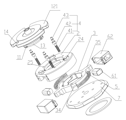
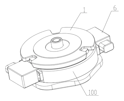
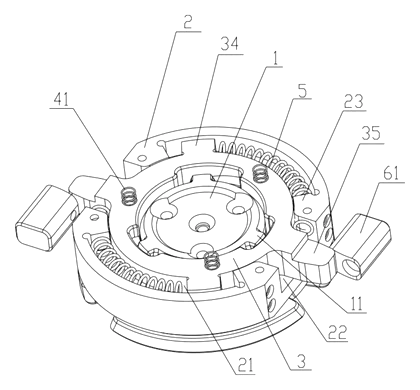
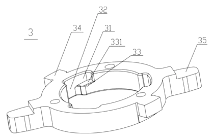
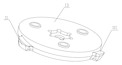
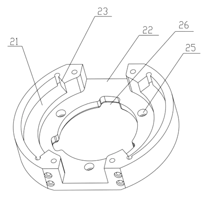
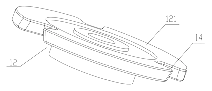
Drawings reproduced from the public patent document for reference.