
Patent CN215602781U
Updated October 26, 2026Vortex Airflow Insect Trap with Filter Isolation
Most fan-based bug zappers shred insects against spinning blades, creating a paste that can scatter bacteria and viruses into the surrounding air. This trap changes the geometry entirely. Peripheral suction inlets feed air past angled guide vanes that aim tangentially toward a central circular suction port. The result is a high-speed vortex inside the treatment chamber. A diversion filter mounted directly over the suction port keeps insects out of the fan assembly below. Instead of hitting a blade, trapped insects are caught in the rotating airstream, circling the filter continuously until they dehydrate and die. The dead insects drop into a removable collection groove rather than sticking to moving parts, keeping the interior cleaner and the exhaust air free of biological debris.
- China utility model - in force
- No filings outside China
- Pest control devices
- Plastic housing, centrifugal fan, mesh filter
Splat! What let you down?
🌪️
Tangential vortex airflow
Guide vanes direct incoming air tangentially to the central port, creating a continuous swirling current inside the chamber.
🛡️
Filter-isolated fan
A diversion filter blocks insects from reaching the fan blades, preventing biological debris from entering the motor.
💨
Dehydration kill method
Trapped insects circle the filter in the high-speed airstream until they dry out, avoiding the splatter of blade-impact traps.
🗑️
Removable collection groove
An internal storage slot catches dried insects for easy disposal without disassembling the fan unit.
Bring this product to market
- ✓ Patent vetted China-only family and legal status checked
- 2 Product brief · now How it works, uses and options written up
- 3 Prototype First samples for buyers to review
- 4 Pilot run Small first batch for launch customers
- 5 Volume production Repeat orders at scale
Buyer interest
– of 100 buyers needed to start prototyping
One click, no sign-up. Each vote is one real visitor, and products with the most interest go to prototyping first.
Build team: no members yet. Need a partner, co-funding or skills to build this? Join and we introduce the team once it forms.
The problem
Standard suction traps pull insects directly into a spinning fan or impeller. The impact shreds the insects into a wet paste that coats the blades and the inner walls. According to the patent, this exposes viruses and bacteria carried by the insects to the passing airstream, which then blows out through the exhaust vent toward the user. Cleaning a blade coated in biological residue is also difficult and unpleasant for consumers.
The solution
The device separates the capture zone from the fan. Air enters through peripheral suction inlets and passes over angled guide vanes that point tangentially toward a circular suction port in the center of the bottom plate. This creates a rotating airflow channel inside the insect treatment device. A diversion filtering device sits directly over the suction port. When the negative pressure generating device pulls air through the port, insects are drawn into the vortex but cannot pass through the filter into the fan. They spin around the filter element until the constant airflow dries them out. The dried remains fall into a collection groove positioned above or beside the airflow channel, keeping the fan assembly clean and the exhaust air free of organic particles.
Who it is for
- Pest control appliance brands looking for a bladeless suction trap to differentiate from standard bug zappers on retail shelves.
- Outdoor hospitality suppliers providing patio equipment for restaurants and hotels where hygiene and odor matter more than raw kill speed.
- Amazon private-label sellers in the home and garden category needing a structurally distinct mosquito trap with clear marketing claims about cleanliness.
- Agricultural research stations requiring traps that collect intact specimens for counting rather than destroying them on impact.
How it works
The main parts
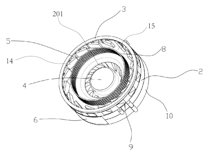
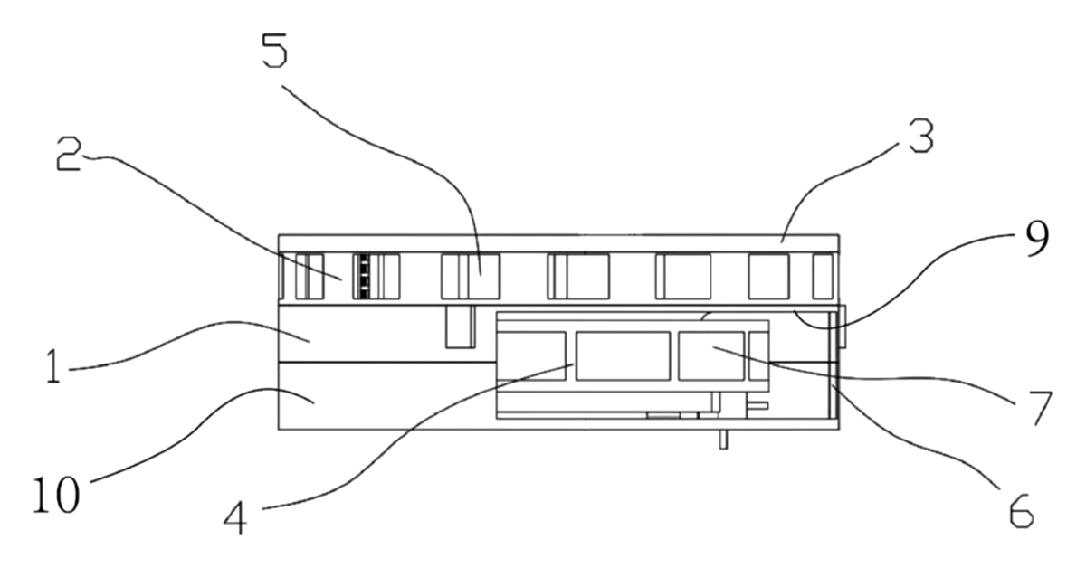
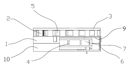
| No. | Part | What it does |
|---|---|---|
| 1 | Negative pressure generating device | Houses the fan assembly and provides the suction force. |
| 2 | Insect treatment device | The upper chamber where the vortex forms and insects are trapped. |
| 3 | Cover | Closes the top of the treatment device; includes a transparent observation part. |
| 4 | Fan assembly | Contains the centrifugal fan, air inlet and air outlet. |
| 5 | Suction inlet | Peripheral openings on the treatment device where air and insects enter. |
| 6 | Air exhaust port | Vents filtered air out of the base. |
| 8 | Diversion filtering device | Blocks insects from the fan; shapes the airflow. Available as straight-tube, dome or combined shapes. |
| 9 | Bottom plate | Forms the floor of the treatment device with the central circular air suction opening (201). |
| 12 | Fixed seat | Supports the fan assembly and connects to the bottom plate. |
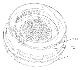
| 13 | Collecting device | Storage grooves that catch dried insects from the vortex. |
| 14 | Flow guide device | Angled vanes extending from the suction inlets toward the interior to create tangential flow. |
| 15 | Airflow channel | The space between the guide vanes and the filter where the vortex rotates. |
| 81 | Air flow adjusting area | A section of the filter wall that directs the vortex height toward the collecting device. |
| 131 | First storage groove | An internal slot with a windward opening (133) to catch insects. |
| 134 | Air flow hole | Holes in the storage groove wall allowing air to pass while retaining insects. |
Operating steps
- Power on the fan assembly - the centrifugal fan draws air through the air inlet, creating negative pressure at the central air suction opening (201) on the bottom plate.
- Air enters the suction inlets - ambient air carrying nearby insects is pulled through the peripheral openings (5) on the side wall of the insect treatment device.
- Guide vanes shape the flow - the flow guide device (14) forces the incoming air to move tangentially relative to the circular suction port, establishing a rotating vortex inside the airflow channel (15).
- Insects are trapped in the vortex - the diversion filtering device (8) physically blocks the insects from being sucked down into the fan. They continue to circle the filter in the high-speed rotating airstream.
- Dehydration occurs - the continuous airflow removes moisture from the trapped insects until they die.
- Collection - dried insects are blown by the vortex into the storage groove opening (133) of the collecting device (13). Air passes through the air flow holes (134) back into the system, while the solid remains stay in the groove for later disposal.
- Exhaust - clean air passes through the filter’s air inlet holes (801), enters the fan’s air inlet (11), and exits through the air outlet (7) and the exhaust port (6) on the fixed seat.
Applications
Backyard patios and decks
Homeowners place the trap near seating areas during summer evenings. The vortex pulls mosquitoes away from people without the loud snapping noise of electric grid zappers, and the enclosed dehydration process prevents the smell of burning insects.
Restaurant outdoor dining
Commercial patios require pest control that does not spray biological debris into the dining space. Because the fan is isolated behind the filter, the exhaust air remains clean, meeting the expectations of food service environments where hygiene is closely monitored.
Camping and RV sites
Portable versions powered by low-voltage DC fans can run from battery packs or vehicle outlets. The absence of fragile UV tubes or high-voltage grids makes the vortex design more resistant to vibration and transport shocks compared to traditional lantern-style zappers.
Greenhouse and nursery monitoring
Growers use suction traps to monitor flying pest populations. The collection groove allows staff to remove dried specimens periodically for identification and counting, supporting integrated pest management routines without introducing chemical sprays near crops.
Livestock barns and stables
Barns accumulate large numbers of flies and gnats. A high-volume centrifugal fan paired with a robust dome filter can process significant air volumes. The sealed fan compartment prevents dust and animal dander from clogging the motor as quickly as open-blade designs.
Where it is less suitable
- Instant-kill requirements - buyers who need insects killed immediately upon entry may prefer high-voltage grid traps, as dehydration takes time.
- Extremely dusty industrial settings - fine particulate can clog the filter’s air inlet holes rapidly, reducing suction unless a pre-filter or frequent cleaning schedule is maintained.
- Silent operation needs - any centrifugal fan generates aerodynamic noise; if absolute silence is required, passive sticky traps remain the only option.
Frequently asked questions
How does the vortex actually kill the insects?
The fan creates negative pressure at the center of the bottom plate, pulling air through the peripheral inlets. Angled guide vanes force this air to travel tangentially, forming a high-speed rotating current inside the chamber. Trapped insects are caught in this vortex and spin continuously around the central filter. According to the patent, the constant fast-moving air removes moisture from the insects until they dehydrate and die, which avoids the need for physical crushing or electric shock.
Do the insects hit the fan blades?
No. The diversion filtering device is mounted directly over the circular air suction opening. It acts as a physical barrier between the vortex chamber and the fan assembly below. Air passes through the filter’s inlet holes into the fan, but the insects remain trapped above the filter in the treatment device.
What shapes of filters are available?
The patent describes three configurations: a straight-tube filter element with square holes, a dome-shaped filter element, and a combined version featuring both a straight cylindrical portion and a dome portion. All variants include air inlet holes to allow airflow while blocking insects.
How are the dead insects removed?
A collecting device is positioned inside or adjacent to the airflow channel. It features a first storage groove with an opening facing the windward side of the vortex. As dried insects circulate, the airflow pushes them into this opening. Air flow holes in the opposite wall let the air continue circulating while the solid remains stay trapped in the groove. The patent also notes the collecting device can be detachable for emptying.
Does it use light to attract bugs?
The patent mentions an optional trap lamp disposed near the suction inlets, with its light emitted outward from the insect treatment device. Additionally, the housing shell can be made of transparent materials to allow the light to pass through effectively. Whether to include a UV or LED attractant is a design choice for production.
Is the device noisy?
The patent specifies a centrifugal fan for generating negative pressure. Noise levels depend entirely on the fan diameter, motor RPM and housing acoustics chosen during product development. These parameters are set in design and confirmed on prototypes to balance suction power against acceptable sound output for indoor or patio use.
Can this design be made and sold in the US?
The patent was filed only in China and is currently in force there, so it does not restrict manufacturing or sales in the US. However, vortex insect traps may be covered by other US patents - see Patent & Production - so we recommend a freedom-to-operate check before volume production.
Are you affiliated with the patent owner?
No. IP2M is an independent design and manufacturing service working from the public patent document.
Request a quote
Click Request a Quote below to see our email address - copy it, or open your email app with a ready-made message. Please mention patent CN215602781U in the subject.
Helpful details to include:
- Your company and channel (pest control brand, Amazon seller, outdoor hospitality supplier, agricultural distributor)
- Target environment (indoor, patio, greenhouse, livestock barn)
- Power preference (AC mains, USB, battery)
- Filter style (straight-tube, dome, or combined)
- Estimated quantity and target price
- Timeline - when you would like samples and the first shipment
You can also reach us at (332) 203-9997.
Explore this product
Interested in building this?
Tell us your target market, quantity and timeline. We reply with options for prototyping, small-batch runs or volume production.
Send your inquiry to
Please put CN215602781U in the subject line and tell us your company, country, estimated quantity and timeline.
Prefer to talk? Call (332) 203-9997.
More product-ready patents
All Garden & Outdoor patents →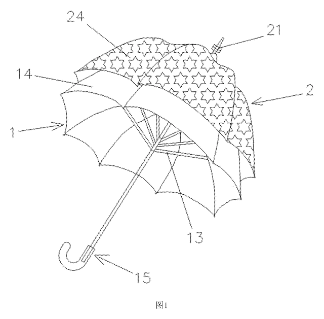
Garden & Outdoor
2-in-1 Parent & Child Umbrella
Full-size umbrella with a nested smaller umbrella on top - a rotating decorative layer that detaches into a kid-size umbrella.
Patent CN205611962U
Garden & Outdoor
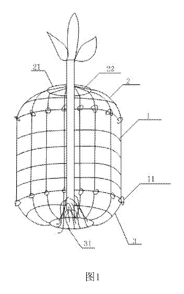
Wire-Mesh Tree Root & Trunk Guard Against Rodents
Three-part wire-mesh guard that protects the roots and lower trunk of young trees from burrowing and gnawing animals.
Patent CN206808261U
Garden & Outdoor
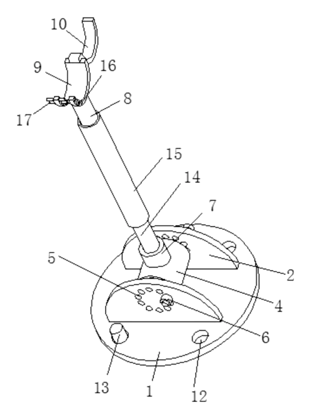
Adjustable-Angle Tree Support Prop
Tree prop with a pinned base, angle-locking hinge, twist-adjust tube and a locking trunk ring.
Patent CN208370491U
Garden & Outdoor
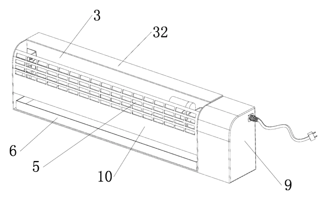
Self-Renewing Glue-Roller Mosquito Trap
UV insect trap with a glue roller that re-coats itself and scrapes the catch into a tray - no glue boards.
Patent CN217038569U
Garden & Outdoor
Cam-Lock Telescopic Pole for Garden Power Tools
Telescopic pole for garden power tools with cam-lever locks and a spring-button, tear-drop head socket.
Patent CN205812889U
Garden & Outdoor
Mosquito Fan That Listens for Mosquitoes Before It Sprays
Fan with a scanning microphone dish that mists repellent only when it hears mosquitoes.
Patent CN208708542U
Browse by category
- Apparel & Accessories (22)
- Baby & Kids (16)
- Bags & Luggage (9)
- Bath & Personal Care (16)
- Car Accessories (10)
- Furniture, Bedding & Storage (12)
- Garden & Outdoor (18)
- Health & Wellness (8)
- Home, Kitchen & Cleaning (24)
- Lighting (12)
- Packaging & Containers (6)
- Pet Products (6)
- Phone & Camera Accessories (4)
- Retail Display (13)
- School, Office & Art (19)
- Sports & Recreation (25)
- Tools & Workshop (27)
- Toys & Games (12)
This page is based on the public patent document CN215602781U, assigned to Beijing Bihe Yida Intellectual Property Consulting Center LP. IP2M is an independent manufacturing service and is not affiliated with, endorsed by or licensed by the patent owner. Images marked as concept renderings are illustrations, not photos of an existing product. Patent status information is provided for reference only and is not legal advice; confirm freedom to operate for your market before production. Full disclaimer.