At a glance
| Patent number | CN215602781U (application CN202120335443) |
| Type | China utility model (实用新型) - protects product shape and structure |
| Original title | Insect killing device (一种昆虫杀灭装置) |
| Patent owner | Beijing Bihe Yida Intellectual Property Consulting Center LP |
| Inventors | Huang Shifu |
| Filing date | 2021-02-05 |
| Grant date | 2022-01-25 |
| Status (China) | In force in China until at most 2031-02-05 (if annual fees are paid) |
| Patent family | Chinese filings only - no US, European, Japanese, PCT or other filings listed |
| Cited by | 2 later documents |
| Source | Google Patents (search for CN215602781U) |
What the claims cover, in plain language
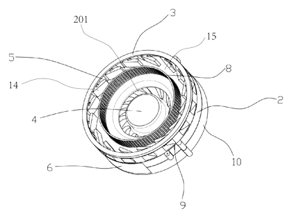
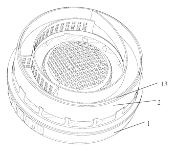
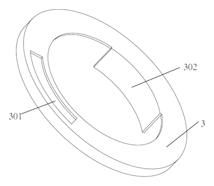
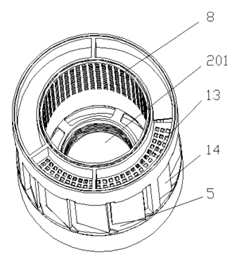
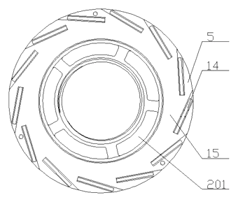
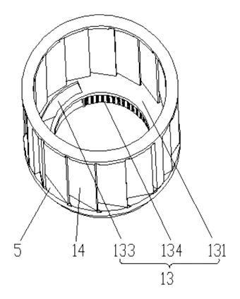
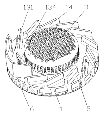
Claim 1 - an insect killing apparatus comprising an insect treatment device with a bottom plate having a circular air suction opening in its center. Suction inlets are arranged around the periphery. Inside, a flow guide device made of multiple guide parts extends from the inlets toward the interior, angled so their direction is basically tangential to the circumference of the suction opening. An airflow channel forms between the guide device and the suction opening. A diversion filtering device is installed at the suction opening. When negative pressure is applied, air enters the channel and forms a rotating airflow, causing sucked insects to rotate with it.
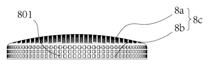
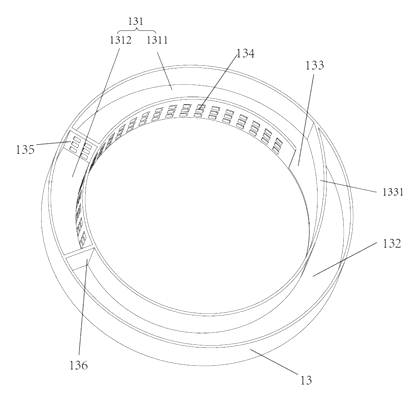
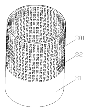
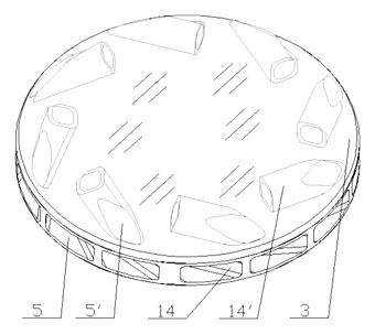
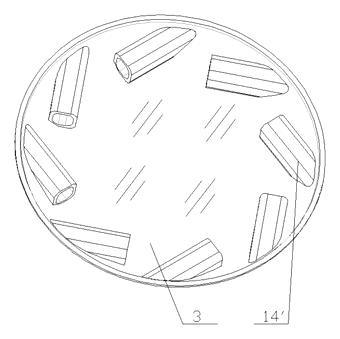
Claim 2 - the flow guide parts are spaced so the airflow direction remains tangential to the rotating path. Claim 3 - a collecting device placed above, radially outside, or below the airflow channel. Claim 4 - part of the filter extends upward vertically, with an air flow adjusting area on its side wall to control the vortex height based on where the collecting device sits. Claim 5 - an air inlet area with multiple holes on the filter wall, communicating with the suction opening. Claim 6 - the guide parts are plate-like or tubular members. Claim 7 - the collecting device has a first storage groove with a windward opening and air flow holes in its opposite wall. Claim 8 - a second receiving groove communicating with the outer periphery near the suction inlets. Claim 9 - a negative pressure generating device connected to the bottom plate, containing a fan with an exhaust port communicating with the suction opening and filter. Claim 10 - a trap lamp near the suction inlets emitting light outward.
This is a simplified reading for orientation only. The legal scope is defined by the exact claim wording in the official Chinese document.
What this means for US production
This patent was filed only in China. It is currently in force in China until at most 2031-02-05 (if annual fees are paid), meaning manufacturing or selling this specific design within China requires the patent owner’s permission. It has no US or other foreign counterpart.
Two points to settle early:
- Other patents may exist. Vortex-based insect traps and fan-suction mosquito killers are actively patented by several consumer electronics and pest control companies in the US, including designs with specific baffle geometries and collection chambers, so a freedom-to-operate (FTO) review of the tangential vane angle and filter placement is needed before tooling.
- Electrical safety. Any device combining a fan motor with an optional UV trap lamp must meet US electrical standards before retail sale.
Customization and manufacturing
What can be customized
| Area | Options |
|---|---|
| Housing shape | Cylindrical, square, or tapered profiles to match brand styling |
| Filter type | Straight-tube square-hole mesh, dome mesh, or combined cylinder-and-dome |
| Fan specification | Centrifugal fan size and RPM to adjust suction volume and noise level |
| Collection system | Internal storage groove, external slide-out drawer, or disposable bag adapter |
| Attractant | Integrated UV trap lamp wavelength, or blank housing for external lure placement |
| Material and color | ABS, PP, or PC plastics; custom colors and surface textures |
| Power input | AC mains adapter, USB 5V DC, or battery compartment |
Things to plan for (US market)
- EPA pesticide device regulations - mechanical insect traps are classified as pesticide devices under FIFRA. They do not require EPA registration, but the establishment manufacturing them must be registered with the EPA, and labeling must comply with 40 CFR Part 156. Claims about killing specific disease-carrying insects must not be exaggerated.
- UL 60335-2-59 or UL 1559 - safety standards for household electrical insect killers or similar appliances, covering motor insulation, enclosure stability and cord strain relief.
- FCC Part 15 - if the fan motor uses a brushless DC controller or if a UV lamp driver emits radio frequency energy above the exemption threshold, FCC testing is required.
- California Prop 65 - plastic resins and UV lamp components must be screened for listed chemicals.
How a project runs
- Inquiry - target insect species, indoor or outdoor use, power source and estimated volume.
- Design - CAD modeling of the treatment chamber, vane angles, filter geometry and fan matching to achieve the required vortex velocity.
- Prototype - 3D-printed or soft-tooled samples tested for airflow pattern, suction rate and collection efficiency.
- Pilot run - injection-molded units assembled for durability testing, noise measurement and regulatory pre-compliance checks.
- Production - mold fabrication, plastic injection, fan and motor sourcing, filter stamping or molding, final assembly and packaging.
Quantities & timeline
The primary tooling investment is the injection mold for the insect treatment device housing and the bottom plate, along with the tooling for the filter element if it is molded rather than stamped from mesh sheet. Centrifugal fans and motors are typically sourced from existing supplier catalogs to avoid custom winding costs. Regulatory testing for EPA device labeling and UL safety adds lead time before the first shipment. Send us your target environment, power requirements, preferred filter style, quantity and target price and we will reply with options.
Patent drawings
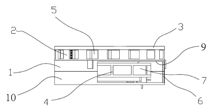
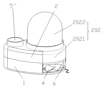
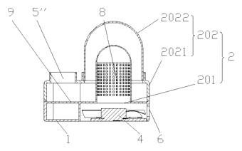
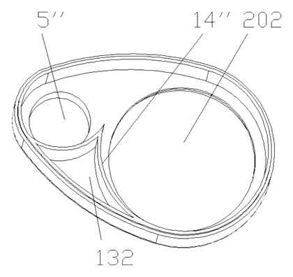
Drawings reproduced from the public patent document for reference.