
Patent CN215789516U
Updated November 5, 2026Wireless Communication Type Electronic Mechanical Torque Wrench with Closed-Loop Control
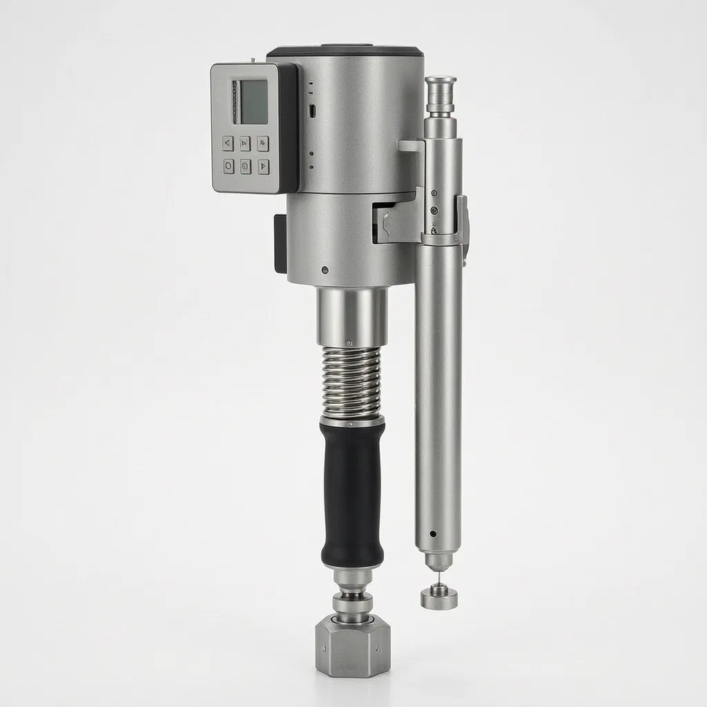
Traditional torque wrenches rely on manual feel or simple click mechanisms, leading to inconsistent readings and no data trail. This patent describes an electronic mechanical torque wrench where a torsion lever inside a sleeve connects to strain gauges and a circuit board with a gyroscope. A motor and speed reducer drive a bolt through a spring and pressure sensor, creating a closed-loop system. When the target torque is reached, the CPU commands the motor to stop or reverse, ensuring precision without manual guesswork. Data is transmitted wirelessly to phones or PCs for logging, while a junction box houses the display, switches, and modular ports for power and internet connectivity.
- China utility model - in force
- No filings outside China
- Industrial tools & automation
- Motorized actuation, wireless data, closed-loop control
Splat! What let you down?
📡
Wireless Data Link
Transmits torque and angle data to smartphones or computers via a communication module.
⚙️
Closed-Loop Motor Control
A motor and speed reducer drive a bolt against a pressure sensor for automated stopping.
🔋
Modular Junction Box
Houses the display, switches, battery, and optional slots for SIM or data cards.
🎯
Auto-Calibration
The system reverses the motor if the pressure sensor exceeds the preset value.
Bring this product to market
- ✓ Patent review Patent family and legal status reviewed in the relevant jurisdictions.
- 2 Product brief · now How it works, uses and options written up
- 3 Prototype First samples for buyers to review
- 4 Pilot run Small first batch for launch customers
- 5 Volume production Repeat orders at scale
Buyer interest
– of 100 buyers needed to start prototyping
One click, no sign-up. Each vote is one real visitor, and products with the most interest go to prototyping first.
Build team: no members yet. Need a partner, co-funding or skills to build this? Join and we introduce the team once it forms.
Patent Rights & Team Participation
Before joining a development team, participants should ensure they have the necessary rights or authorization to participate in the project.
Participation is generally appropriate where:
- You own the relevant patent rights or have obtained permission or a license from the rights holder.
- The relevant patent rights have expired or have been legally invalidated in the jurisdictions where the planned activities will take place.
- The planned development, manufacturing, and commercialization activities have been independently assessed and do not infringe applicable patent rights in the relevant jurisdictions.
Important: Being located outside a country where a patent is protected does not automatically exempt you from patent infringement risks. Patent rights may apply based on where development, manufacturing, use, sale, or import activities take place.
IP2M does not grant any patent license or authorization through team participation. Joining a project does not provide permission to use, manufacture, or commercialize patented technology.
The problem
Manual torque wrenches depend on the operator’s physical sensation or a mechanical click to signal when the target torque is reached. This approach introduces variability because human perception changes with fatigue, angle, and experience. In industrial settings, there is often no digital record of the applied torque, making quality assurance and traceability difficult. Furthermore, standard electronic wrenches may lack integrated mechanisms for automated correction, requiring the user to manually adjust their grip or technique if they overshoot the limit. Without a closed-loop feedback system connected to both the mechanical actuator and a wireless data logger, maintaining consistent, documented torque values across multiple fastening points remains labor-intensive and prone to error.
The solution
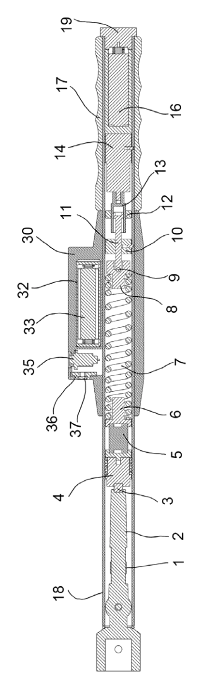
- Torsion Lever and Strain Gauges: A torsion lever (2) runs inside the main sleeve (18). Strain gauges (1) are fixed to the outer side of this lever and connect to a circuit board (31) equipped with a gyroscope.
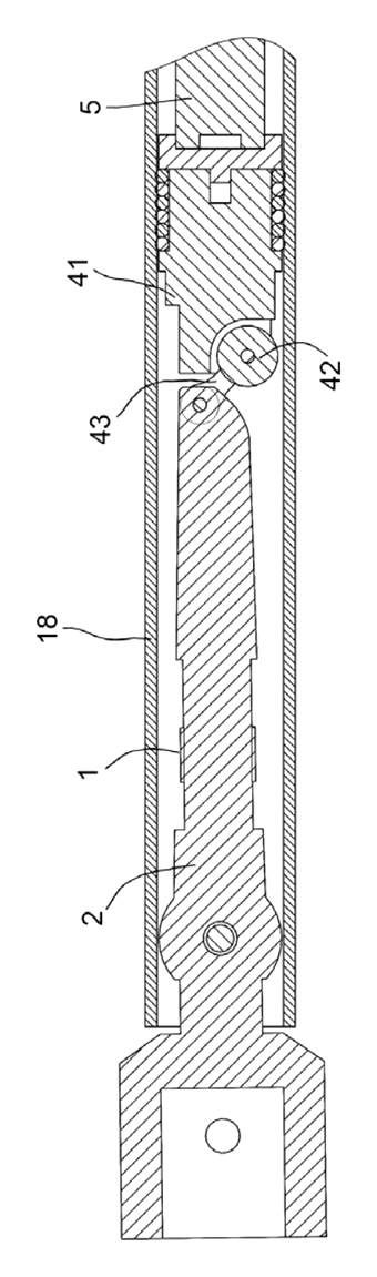
- Sliding Body and Pressure Sensor: One end of the torsion lever connects to a sliding body module (4), which includes a roller sliding body (41) and pulley (42). A tripping block (3) sits between the sliding body and the lever. A pressure sensor (5) is mounted on the sliding body.
- Spring and Bolt Mechanism: The pressure sensor faces a front spring cover (6), which holds a spring (7). The rear of the spring connects to a rear spring cover (8), then to a steel ball (9) and a bolt (11).
- Motorized Actuation: The bolt passes through a counter-force arm fixing body (10) and bearing (12), connecting to a sleeve (13) and a speed reducer driven by a motor (14).
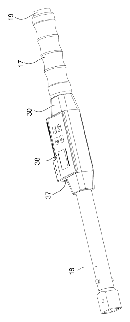
- Junction Box Interface: A junction box (30) on the sleeve’s exterior houses the circuit board, battery box (32), display (38), and switch mask (39). It includes ports like a Ramo interface (35) and connector base (36).
- Closed-Loop Control: The central processing unit receives data from the pressure sensor and torque/angle sensors. If the preset value is reached, it commands the motor to stop; if exceeded, it reverses the motor to relieve pressure.
Who it is for
- Industrial Assembly Lines: Brands needing automated torque verification and data logging for critical fasteners in automotive or machinery production.
- Field Service Technicians: Wholesalers supplying technicians who require wireless transfer of maintenance records to central servers or mobile devices.
- Quality Assurance Teams: Companies implementing ISO standards where traceable, digital proof of torque application is mandatory for compliance audits.
- Tool Rental Agencies: Operators offering high-value smart tools that can track usage hours and calibration status remotely via SIM-enabled modules.
How it works
The main parts
| No. | Part | What it does |
|---|---|---|
| 80 | Torque Wrench Main Body | The external housing and handle structure. |
| 18 | Sleeve | Runs through the body, holding the torsion lever. |
| 2 | Torsion Lever | Flexes under load; measured by strain gauges. |
| 1 | Strain Gauge | Converts mechanical deformation into electrical signals. |
| 31 | Circuit Board | Processes signals; contains gyroscope and CPU. |
| 4 | Sliding Body Module | Transfers motion to the pressure sensor. |
| 5 | Pressure Sensor | Measures force exerted by the spring compression. |
| 7 | Spring | Provides resistance; compressed by the motor-driven bolt. |
| 14 | Motor | Drives the speed reducer to rotate the bolt. |
| 30 | Junction Box | Houses display, battery, and communication ports. |
| 38 | Display | Shows real-time torque and angle data. |
Operating Steps
- Setup: The user sets the target torque value via the switch mask (39) on the junction box.
- Application: As the tool engages the fastener, the torsion lever (2) twists. Strain gauges (1) detect this twist, while the motor (14) drives the bolt (11) to compress the spring (7) against the pressure sensor (5).
- Feedback Loop: The pressure sensor sends data to the A/D conversion module and central processing unit. The CPU compares this against the preset value.
- Automatic Stop/Correction: When the preset value is reached, the CPU commands the motor to stop. If the sensor detects an overshoot, the CPU reverses the motor slightly to reduce pressure until the value stabilizes.
- Data Transmission: The communication module transmits the final torque and angle data wirelessly to a smartphone (81) or computer via network 83.
Applications
Automotive Engine Assembly
In engine blocks, cylinder head bolts must be tightened to exact specifications to prevent leaks or failure. This wrench provides a digital log of each bolt’s torque, allowing manufacturers to verify that every fastener met the spec before the vehicle leaves the line. The wireless upload ensures supervisors have real-time visibility into assembly progress.
Aerospace Maintenance
Aircraft maintenance requires strict adherence to torque limits on structural components. The closed-loop control prevents accidental over-torquing, which could damage sensitive aluminum alloys. Technicians can use the SIM card module option to transmit maintenance records directly to airline databases, satisfying regulatory audit requirements without paper logs.
Heavy Machinery Repair
When repairing excavators or cranes, large bolts often require significant torque. The motorized assistance reduces physical strain on workers while ensuring consistency. The gyroscope and angle sensor help monitor joint rotation, providing additional data points for diagnosing wear or alignment issues during field repairs.
Electronics Manufacturing
Small, delicate screws in server racks or consumer electronics need precise low-torque application. The strain gauge sensitivity allows for fine control, preventing stripped threads. The wireless capability lets factory managers track which station applied which torque setting, aiding in root-cause analysis if a component fails later.
Where it is less suitable
- Simple DIY Home Repairs: The complexity, cost, and need for charging/data setup make it excessive for occasional household tasks where a basic manual wrench suffices.
- Extreme Temperature Environments: While robust, the battery and electronic components may require specific thermal management not detailed in the patent for sub-zero or high-heat industrial zones.
- High-Speed Continuous Production: For lines requiring thousands of fasteners per hour, fully automated robotic arms with integrated torque feedback may be faster than handheld operation, even with motor assist.
Patent & Production
At a glance
| Patent number | CN215789516U (application CN202122266344) |
| Type | China utility model (实用新型) - protects product shape and structure |
| Original title | Wireless Communication Type Electronic Mechanical Torque Wrench (无线通讯型电子机械扭矩扳手) |
| Patent owner | Shaanxi Knowns Intelligent Industrial Equipment Co ltd |
| Inventors | Liu Wenming |
| Filing date | 2021-09-18 |
| Grant date | 2022-02-11 |
| Status (China) | In force - valid until at most 2031-09-18, provided annual fees are paid |
| Patent family | Public record shows Chinese filings only - no US, European, Japanese, PCT or other filings listed |
| Cited by | 5 later documents |
| Source | Google Patents (search for CN215789516U) |
What the claims cover, in plain language
Claim 1 defines a torque wrench main part (80) with a sleeve (18) running through it and a handle (17). Inside the sleeve is a torsion lever (2) with a strain gauge (1) connected to a circuit board (31) containing a gyroscope. The lever connects to a sliding body module (4) with a pressure sensor (5). A spring (7) is positioned between the sensor and a bolt (11) driven by a motor (14) via a speed reducer. A tripping block (3) is located between the sliding body and the lever.
Claim 2 specifies the electronics architecture: the pressure sensor connects to an A/D module, which links to torque and angle sensors and a central processing unit. The CPU controls the display (38), motor (14), communication module, and alarm systems.
Claim 3 details the junction box (30) attached to the sleeve, housing the circuit board, battery box (32), Ramo interface (35), connector base (36), display (38), and switch mask (39).
Claim 4 describes internal cavities within the junction box for installing optional modules.
Claim 5 positions the battery bin (15) next to the motor.
Claim 6 breaks down the sliding body module into a roller sliding body (41), pulley (42), and connecting piece (43).
Claim 7 establishes wireless communication between the CPU and external devices like smartphones (81) or computers.
This is a simplified reading for orientation only. The legal scope is defined by the exact claim wording in the official Chinese document.
What this means for US production
This patent was filed in China and is currently in force, so making or selling this specific design in China requires the owner’s permission. The public record shows no US or other foreign counterpart.
Two points to settle early:
- Other patents may exist. Atlas Copco Industrial Technique Ab has cited this document in WO2026133112A1, indicating active patent activity in this field. A freedom-to-operate (FTO) review is needed to ensure the motorized closed-loop control and wireless data features do not infringe on existing US patents held by major tool manufacturers.
- Component sourcing. The integration of strain gauges, gyroscopes, and custom motors requires reliable supply chains for electronic components that meet industrial durability standards.
Customization and manufacturing
What can be customized
| Area | Options |
|---|---|
| Drive Size | 1/4", 3/8", 1/2", 3/4" square drives depending on application |
| Torque Range | Low to high capacity based on motor size and gear ratio |
| Communication | Bluetooth, Wi-Fi, or cellular (SIM module) as described in Claim 4 |
| Display | LCD or OLED screen size and resolution within the junction box cavity |
| Battery | Capacity and chemistry (Li-ion recommended) within the battery bin (15) |
| Housing Material | Die-cast aluminum or reinforced polymer for the main body |
Things to plan for (US market)
- FCC Part 15 - Any wireless transmitter (Bluetooth/Wi-Fi/SIM) must undergo certification for electromagnetic compatibility and radio frequency exposure.
- UL 60950 / IEC 62368 - Safety standards for information technology equipment, applicable due to the presence of lithium batteries and electronics.
- OSHA Guidelines - While not a direct certification, ergonomic assessments may be required for industrial tools used repeatedly.
- RoHS Compliance - Restriction of Hazardous Substances applies to the PCB, solder, and plastics used in the assembly.
How a project runs
- Inquiry - Define torque range, drive size, and desired wireless protocols.
- Design - Finalize PCB layout, motor selection, and mechanical tolerances for the torsion lever.
- Prototype - Build functional samples using machined parts and off-the-shelf motors/sensors.
- Pilot Run - Test accuracy, repeatability, and wireless stability; validate battery life.
- Production - Mold housings, assemble PCBs, calibrate sensors, and pack units.
Quantities & timeline
Molds for the die-cast aluminum body and plastic junction box are the primary lead items. PCB assembly and motor integration require specialized testing stations. Calibration software development is critical for the closed-loop system. Send us your torque range, drive size, wireless protocol, quantity and target price and we will reply with options.
Patent drawings
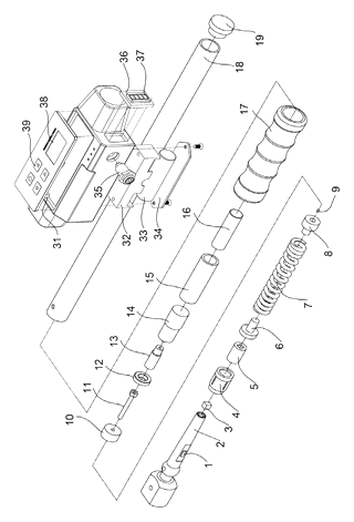
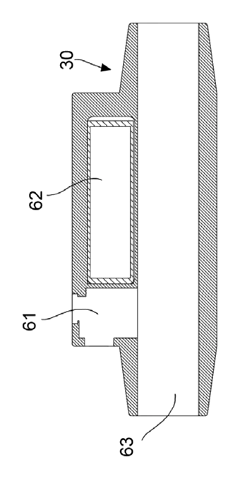
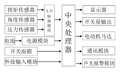
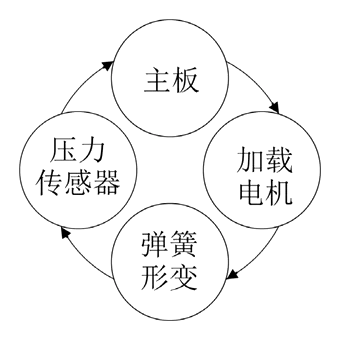
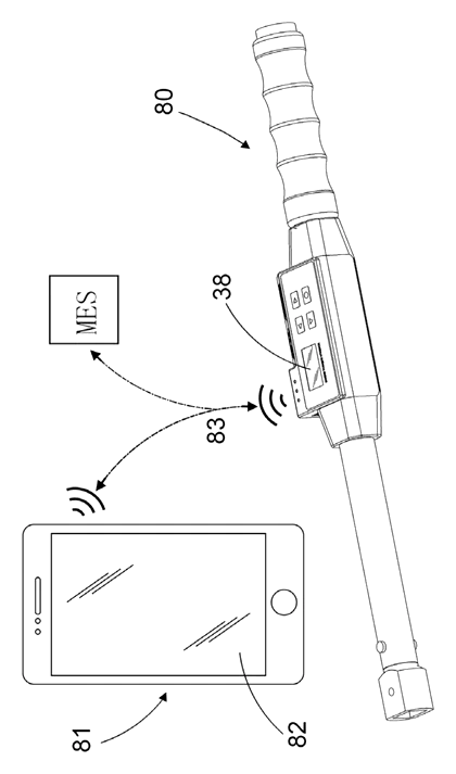
Drawings reproduced from the public patent document for reference.
Production notes
Tooling and process
Die-cast aluminum likely forms the main body and handle for strength and heat dissipation. Stamped steel may be used for internal brackets or shield plates. Glass-filled nylon injection molding is typical for the junction box cover to provide insulation and impact resistance. Machining is necessary for the torsion lever and bolt interfaces to ensure precise fitment.
Cost drivers
Material and heat treatment costs for the torsion lever are typically significant due to stress requirements. Cutting edge machining for the motor shaft and bearings adds precision costs. The number of stamping dies affects tooling investment if metal shields are used. Surface finish on the exterior impacts aesthetic appeal and corrosion resistance.
Prototyping path
We would typically start with a 3D-printed handle and junction box to verify ergonomics and assembly fit. Use machined or off-the-shelf blades for initial torque tests. Create heat-treatment trial coupons to validate lever durability. Build a functional sample with calibrated sensors before moving to tooling.
What we would change before tooling
We would likely review the spring rate consistency and pivot pin wear points early. Ensure wire routing and strain relief accommodate the rotating motor assembly. Verify that the coating wear resistance meets industrial standards for frequent handling. Check motor mount cracking risks under high-torque loads.
Common failure points
Edge hardness below spec on the drive square can strip bolts. Spring-back or kickback may occur if the closed-loop response time is too slow. Shaft and bearing alignment errors cause vibration and noise. Battery compartment security must prevent accidental ejection during drops. Charging safety circuits are critical to prevent thermal runaway.
Frequently asked questions
How does the automatic stop work?
The wrench uses a closed-loop system. A pressure sensor measures the force applied by a motor-driven bolt compressing a spring. When the central processing unit detects that the preset torque value is reached, it commands the motor to stop. If the value is exceeded, the motor reverses slightly to reduce pressure.
Can it send data to my phone?
Yes. The patent describes a communication module that connects the central processing unit to a smartphone or computer wirelessly. This allows you to view torque and angle data in real-time or save it for quality records.
Does it need calibration?
The design includes strain gauges and pressure sensors that require calibration. The system supports automatic calibration routines where the CPU adjusts for sensor drift, but periodic manual verification against a master standard is recommended for industrial use.
How long does the battery last?
The patent mentions a battery box and bin but does not specify capacity or runtime. Battery life depends on the cell choice, motor efficiency, and frequency of wireless transmission. Typical industrial tools aim for full-shift operation.
Is the motor strong enough for high torque?
The motor drives a speed reducer to increase torque output. The patent describes the mechanical linkage but does not list maximum torque ratings. High-torque applications require selecting a motor and gearbox combination appropriate for the desired Newton-meter range.
Can I add a SIM card?
Yes. Claim 4 describes cavities in the junction box for optional modules, including a SIM card module for internet-of-things connectivity. This allows data transmission via mobile networks rather than just local Wi-Fi or Bluetooth.
Can this design be made and sold in the US?
The patent is in force in China, and the public record shows no US counterpart. Therefore, this specific patent does not restrict sales in the US. However, other US patents may exist in the smart tool field, so a freedom-to-operate check is advised before volume production.
Are you affiliated with the patent owner?
No. IP2M is an independent design and manufacturing service working from the public patent document.
Request a quote
Click Request a Quote below to see our email address - copy it, or open your email app with a ready-made message. Please mention patent CN215789516U in the subject.
Helpful details to include:
- Your company and channel (industrial distributor, automotive supplier, tool brand)
- Target torque range and drive size
- Wireless protocol preference (Bluetooth, Wi-Fi, Cellular)
- Quantity and estimated annual volume
- Certification needs (FCC, UL, etc.)
- Timeline - when you would like samples and the first shipment
You can also reach us at (332) 203-9997.
Page editor: Emily Zhang, Product Editor · IP2M
Last updated November 5, 2026. If something on this page looks wrong, email [email protected] and we will check it against the patent.
Interested in building this?
Tell us your target market, quantity and timeline. We reply with options for prototyping, small-batch runs or volume production.
Send your inquiry to
Please put CN215789516U in the subject line and tell us your company, country, estimated quantity and timeline.
Prefer to talk? Call (332) 203-9997.
More product-ready patents
All Tools & Workshop patents →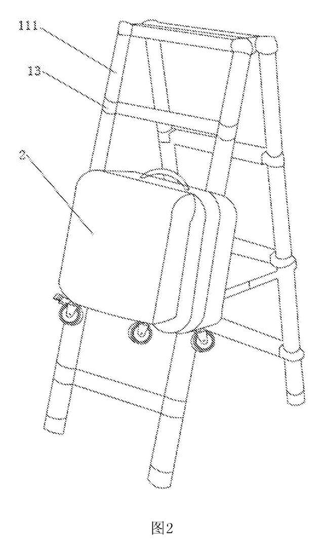
Tools & Workshop
Rolling Tool Box with Telescoping Step Ladder
Telescoping A-frame ladder with an attached rolling tool box that slides to your working height.
Patent CN206290197U
Tools & Workshop
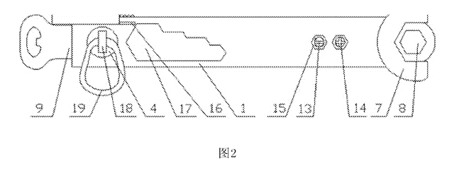
Folding 3-Handle Wrench Multi-Tool
Folding three-handle wrench multi-tool with magnetic screwdriver bits, saw, file and bottle opener.
Patent CN205290875U
Tools & Workshop
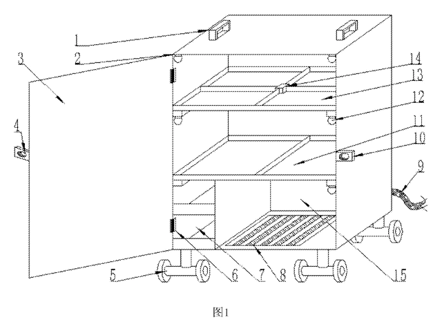
Rolling Auto-Repair Tool Cabinet with Built-In Lights
Lockable rolling tool cabinet for car repair with interior lights, a lubricant tray, parts drawers and a tool bay.
Patent CN205989314U
Tools & Workshop
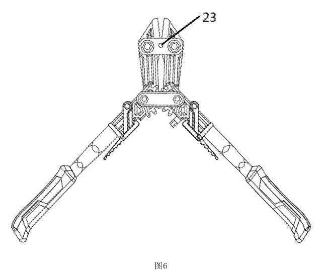
Wide-Opening Folding Bolt Cutter
Bolt cutter with linked, gear-meshing handles that open up to 190° and fold in half for storage.
Patent CN207206226U
Tools & Workshop
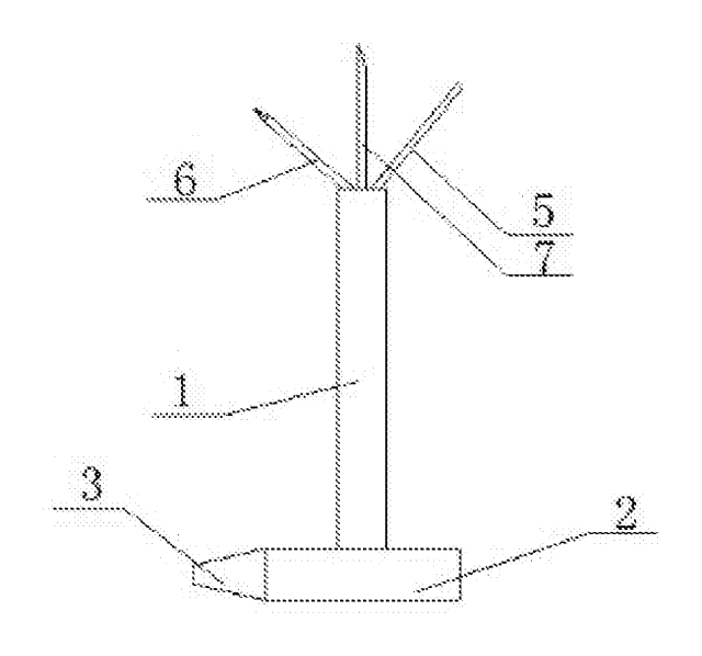
Nail-Holding Hammer with Fold-Out Drivers
Hammer with a nail-holding T-slot in the head and fold-out drivers stored in the handle.
Patent CN205254927U
Tools & Workshop
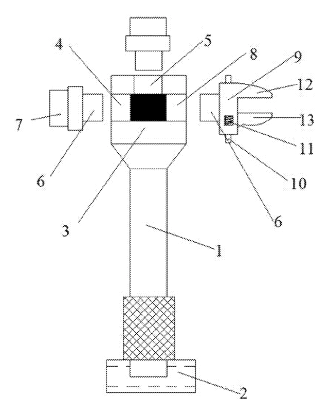
Modular Wrench with Screw-On Heads
Wrench handle with a three-way threaded hub for screw-on adjustable and hex heads, plus a pipe sleeve.
Patent CN206216564U
Browse by category
- Apparel & Accessories (41)
- Baby & Kids (26)
- Bags & Luggage (15)
- Bath & Personal Care (27)
- Car Accessories (22)
- Furniture, Bedding & Storage (21)
- Garden & Outdoor (29)
- Health & Wellness (12)
- Home, Kitchen & Cleaning (44)
- Lighting (21)
- Packaging & Containers (11)
- Pet Products (10)
- Phone & Camera Accessories (8)
- Retail Display (22)
- School, Office & Art (31)
- Sports & Recreation (40)
- Tools & Workshop (49)
- Toys & Games (20)
This page is based on the public patent document CN215789516U, assigned to Shaanxi Knowns Intelligent Industrial Equipment Co ltd. IP2M is an independent manufacturing service and is not affiliated with, endorsed by or licensed by the patent owner. Images marked as concept renderings are illustrations, not photos of an existing product. Patent status information is provided for reference only and is not legal advice; confirm freedom to operate for your market before production. Full disclaimer.