
Patent CN216307484U
Updated October 30, 2026Foldable Plant Growth Light with Central Power Box
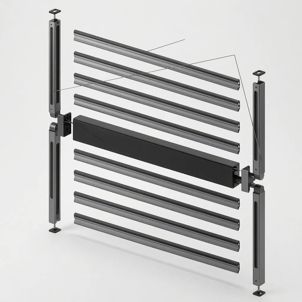
Plant growth lights used in greenhouses and indoor farms face constant moisture. When the power supply and control electronics sit on the outside of the fixture, humidity can reach them over time. This design moves the DC constant current distributor and the dimming controller inside the central connecting beam of a foldable frame. Sealed end covers bolt onto both ends of the beam column, isolating the electronics from the surrounding air. The main frame and sub-frame share the same structure and rotate on hollow shafts built into hinged end caps, allowing the fixture to fold for transport or storage while the wiring passes safely through internal channels.
- China utility model - lapsed
- No filings outside China
- Horticultural lighting
- Sealed central power beam, foldable aluminum frames
Splat! What let you down?
📦
Central power box
The DC constant current distributor and dimming controller are mounted inside the connecting beam column.
💧
Sealed electronics
Bolted sealing end covers isolate the internal components from the humid growing environment.
🔄
Foldable frame
Identical main and sub-frame assemblies rotate on hollow shafts for compact transport and storage.
🔌
Internal wiring path
Cables pass through hollow rotating shafts and threading channels, keeping connections enclosed.
Bring this product to market
- ✓ Patent vetted China-only family and legal status checked
- 2 Product brief · now How it works, uses and options written up
- 3 Prototype First samples for buyers to review
- 4 Pilot run Small first batch for launch customers
- 5 Volume production Repeat orders at scale
Buyer interest
– of 100 buyers needed to start prototyping
One click, no sign-up. Each vote is one real visitor, and products with the most interest go to prototyping first.
Build team: no members yet. Need a partner, co-funding or skills to build this? Join and we introduce the team once it forms.
The problem
Horticultural lighting fixtures operate in environments where water vapor, nutrient mist, and high humidity are constant. In many conventional plant lamps, the power supply and dimming electronics are mounted externally or attached directly to the light bars. Over time, moisture reaches these components, which can lead to corrosion, short circuits, or failure of the control boards. Additionally, large fixed-frame grow lights are difficult to ship and store because their rigid structures take up significant volume, increasing freight costs for buyers who purchase in bulk.
The solution
This utility model addresses those issues by placing the sensitive electrical components inside a central structural element.
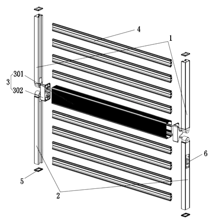
- A main frame assembly and a sub-frame assembly, built with the same structure, form the body of the lamp. Each assembly consists of two oppositely arranged main borders (1) or sub-borders (2).
- At the opposing ends of these borders, connecting ends (201) are installed. These ends allow the two frame assemblies to be rotatably connected through a connecting beam (3), enabling the entire fixture to fold.
- The connecting beam acts as the central power box. It comprises a beam column (301) and sealed end covers (302) fixed to both ends of the beam column by bolts.
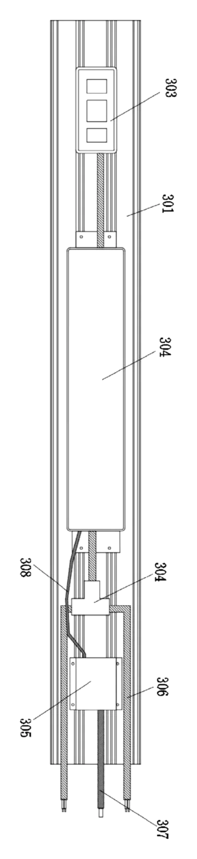
- Inside the beam column, a DC constant current distributor (304) and a dimming controller (305) are installed. The sealed end covers isolate these components from the outside humid environment.
- Light bar frames (4) are fixed between the borders at equal distances from top to bottom to hold the individual light strips.
- The opposite ends of the frames are closed by waterproof end covers (5), and internal wiring routes through the hollow shafts of the hinges into the frames.
Who it is for
- Commercial greenhouse operators who need reliable lighting that withstands high-humidity conditions without frequent electronic failures.
- Indoor vertical farm brands looking for fixtures that fold down to reduce shipping volume and simplify installation between tight rack levels.
- Horticultural lighting wholesalers sourcing products with integrated drivers to offer simpler plug-and-play setups to retail growers.
- Amazon sellers in the garden category seeking differentiated grow lights with a sealed power compartment and a folding mechanism for easier consumer packaging.
How it works
The main parts
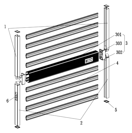
| No. | Part | What it does |
|---|---|---|
| 1 | Main border | Forms the outer frame of the main assembly. |
| 2 | Sub-border | Forms the outer frame of the sub-assembly. |
| 201 | Connecting end | Joins the frame borders to the central beam and allows rotation. |
| 2011 | Hinged end cap | Seals the frame end and houses the rotating shaft. |
| 2012 | Hollow rotating shaft | Provides the pivot point and a path for internal wiring. |
| 2013 | Threading channel | Routes cables from the shaft into the inside of the frame. |
| 2014 | Rubber ring | Seals the hinge area, featuring arc transitions at the corners. |
| 3 | Connecting beam | The central structural and electrical hub. |
| 301 | Beam column | Houses the distributor and controller. |
| 302 | Sealed end cover | Bolts to the beam column to enclose the electronics. |
| 3021 | End mounting position | Integrally formed on the end cover to fit the connecting end. |
| 3022 | Sleeve | Matches the rotating shaft; includes a threaded hole for a bolt. |
| 3023 | Wire hole | An arc-shaped opening with rounded corners for cables to exit the beam. |
| 303 | Power protection switch circuit | Mounted on the back of the beam column. |
| 304 | DC constant current distributor | Splits and regulates power to the frames. |
| 305 | Dimming controller | Adjusts light output based on signals. |
| 306 | Conductive cables | Carry power from the distributor to the PCB tapping circuit boards. |
| 307 | Data transmission cable | Connects the external dimming panel to the controller. |
| 308 | Signal transmission line | Links the dimming controller to the distributor’s control circuit. |
| 309 | Splitter | Taps the power output into two conductive cables. |
| 4 | Light bar frame | Holds the LED strips at equal distances. |
| 5 | Waterproof end cover | Seals the far ends of the main and sub-frames. |
| 6 | Dimming circuit panel | External interface for adjusting the light. |
Operating steps
- Unfold the fixture - Rotate the main frame and sub-frame outward from the connecting beam until they lie flat. The hollow rotating shafts (2012) inside the hinged end caps (2011) pivot within the sleeves (3022) of the sealed end covers (302).
- Connect power - Plug the commercial power cord into the power protection switch circuit (303) on the back of the beam column (301).
- Distribute electricity - The switch circuit feeds the DC constant current distributor (304). The distributor uses a splitter (309) to send power through two conductive cables (306).
- Route internally - The cables pass through the wire holes (3023) in the sleeves, travel through the hollow rotating shafts (2012), and enter the threading channels (2013) to reach the PCB tapping circuit boards inside the main and sub-borders. Needle-type terminals welded to the boards connect to each light bar frame (4).
- Adjust brightness - Use the dimming circuit panel (6) on the sub-frame. It sends data via a transmission cable (307) to the dimming controller (305) inside the beam, which then signals the distributor (304) through a signal line (308) to adjust the current.
Applications
Commercial greenhouses
Greenhouse operators run lighting during dark winter months when condensation is heavy. Placing the driver and dimmer inside the sealed central beam prevents moisture from reaching the electronics, reducing maintenance stops across long rows of crops.
Indoor vertical farms
Vertical farming racks have limited clearance between shelves. A foldable fixture can be collapsed, slid into narrow spaces, and unfolded into position, making installation faster than handling rigid, single-piece bars.
Retail grow light kits
Home growers buying kits online often struggle with bulky packaging. The folding mechanism reduces the box size for e-commerce fulfillment, while the integrated power box means the user does not need to hang a separate heavy driver.
Nursery propagation rooms
Propagation requires consistent light levels controlled by timers or environmental sensors. The external dimming panel connects directly to the sealed internal controller, allowing automated adjustments without exposing the control logic to the high-humidity rooting environment.
Research and university botanical labs
Lab environments require precise, repeatable lighting conditions. The central DC constant current distributor ensures even power delivery to all light bar frames, while the sealed design protects sensitive test parameters from ambient moisture fluctuations.
Where it is less suitable
- High-intensity discharge (HID) replacements requiring massive heat sinks - this frame structure is designed for LED light bars; large thermal masses may exceed the folding hinge capacity.
- Fully submerged aquaculture lighting - the seals protect against humidity and mist, but the patent does not describe submersion ratings.
- Single-bar linear applications - the dual-frame folding design is intended for wide coverage areas, not narrow single-strip setups.
Frequently asked questions
How does the central power box work?
The DC constant current distributor and the dimming controller are mounted inside the hollow beam column that connects the two frame halves. Bolted sealed end covers close both sides of the column, keeping the electronics enclosed away from the plants.
Why is the lamp designed to fold?
The main frame and sub-frame are identical structures joined by hinged end caps that rotate on hollow shafts fitted into the central beam. Folding the fixture reduces its footprint for shipping and makes it easier to install in tight greenhouse aisles or vertical racks.
How do the wires pass through the hinge without breaking?
The rotating shaft inside the hinged end cap is hollow. Cables exit the central beam through arc-shaped wire holes with rounded corners, travel through the hollow shaft, and enter the frame via a threading channel. A rubber ring with arc transitions seals the joint.
Is the fixture protected against greenhouse humidity?
Yes. The sealed end covers bolt tightly to the beam column, creating an isolated environment for the power and control electronics. The far ends of the frames are closed by waterproof end covers, and the hinge joints use rubber rings to block moisture entry.
How is the light intensity adjusted?
A dimming circuit panel mounted on the outside of the sub-frame sends signals through a data transmission cable to the dimming controller inside the sealed beam. The controller then signals the DC distributor to adjust the current sent to the LED light bars.
What holds the LED strips in place?
Light bar frames are fixed between the main and sub-borders at equal distances from top to bottom. Needle-type electric connection plug-in terminals welded to internal PCB tapping circuit boards extend outward to connect with each light bar frame.
Can this design be made and sold in the US?
The patent was filed only in China and is lapsed (terminated for non-payment of annual fees, recorded 2025-12-19), so it does not restrict the design in the US or in China. Horticultural lighting may be covered by other US patents - see Patent & Production - so we recommend a freedom-to-operate check before volume production.
Are you affiliated with the patent owner?
No. IP2M is an independent design and manufacturing service working from the public patent document.
Request a quote
Click Request a Quote below to see our email address - copy it, or open your email app with a ready-made message. Please mention patent CN216307484U in the subject.
Helpful details to include:
- Your company and channel (greenhouse operator, vertical farm brand, horticultural wholesaler, Amazon seller)
- Frame dimensions and target wattage
- LED spectrum requirements (vegetative, flowering, or full-cycle)
- Dimming interface preference (0-10V, digital, or manual panel)
- Estimated quantity and target price
- Timeline - when you would like prototypes and the first shipment
You can also reach us at (332) 203-9997.
Explore this product
Interested in building this?
Tell us your target market, quantity and timeline. We reply with options for prototyping, small-batch runs or volume production.
Send your inquiry to
Please put CN216307484U in the subject line and tell us your company, country, estimated quantity and timeline.
Prefer to talk? Call (332) 203-9997.
More product-ready patents
All Garden & Outdoor patents →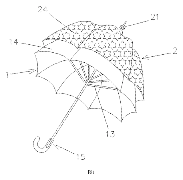
Garden & Outdoor
2-in-1 Parent & Child Umbrella
Full-size umbrella with a nested smaller umbrella on top - a rotating decorative layer that detaches into a kid-size umbrella.
Patent CN205611962U
Garden & Outdoor
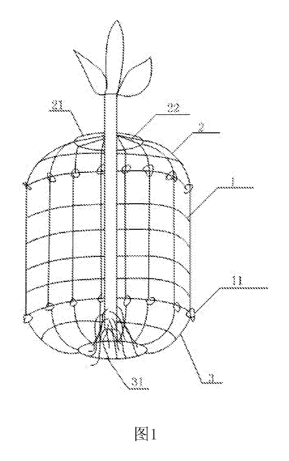
Wire-Mesh Tree Root & Trunk Guard Against Rodents
Three-part wire-mesh guard that protects the roots and lower trunk of young trees from burrowing and gnawing animals.
Patent CN206808261U
Garden & Outdoor
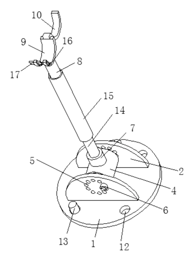
Adjustable-Angle Tree Support Prop
Tree prop with a pinned base, angle-locking hinge, twist-adjust tube and a locking trunk ring.
Patent CN208370491U
Garden & Outdoor
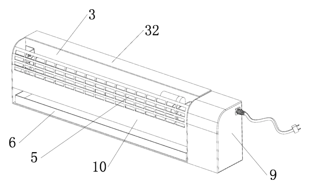
Self-Renewing Glue-Roller Mosquito Trap
UV insect trap with a glue roller that re-coats itself and scrapes the catch into a tray - no glue boards.
Patent CN217038569U
Garden & Outdoor
Cam-Lock Telescopic Pole for Garden Power Tools
Telescopic pole for garden power tools with cam-lever locks and a spring-button, tear-drop head socket.
Patent CN205812889U
Garden & Outdoor
Mosquito Fan That Listens for Mosquitoes Before It Sprays
Fan with a scanning microphone dish that mists repellent only when it hears mosquitoes.
Patent CN208708542U
Browse by category
- Apparel & Accessories (22)
- Baby & Kids (16)
- Bags & Luggage (9)
- Bath & Personal Care (16)
- Car Accessories (10)
- Furniture, Bedding & Storage (12)
- Garden & Outdoor (18)
- Health & Wellness (8)
- Home, Kitchen & Cleaning (24)
- Lighting (12)
- Packaging & Containers (6)
- Pet Products (6)
- Phone & Camera Accessories (4)
- Retail Display (13)
- School, Office & Art (19)
- Sports & Recreation (25)
- Tools & Workshop (27)
- Toys & Games (12)
This page is based on the public patent document CN216307484U, assigned to Shenzhen Ruiwei Zhilian Technology Co ltd. IP2M is an independent manufacturing service and is not affiliated with, endorsed by or licensed by the patent owner. Images marked as concept renderings are illustrations, not photos of an existing product. Patent status information is provided for reference only and is not legal advice; confirm freedom to operate for your market before production. Full disclaimer.