
Patent CN216468203U
Updated November 6, 2026Adjustable Cup Holder with Spring-Loaded Indexing Mechanism
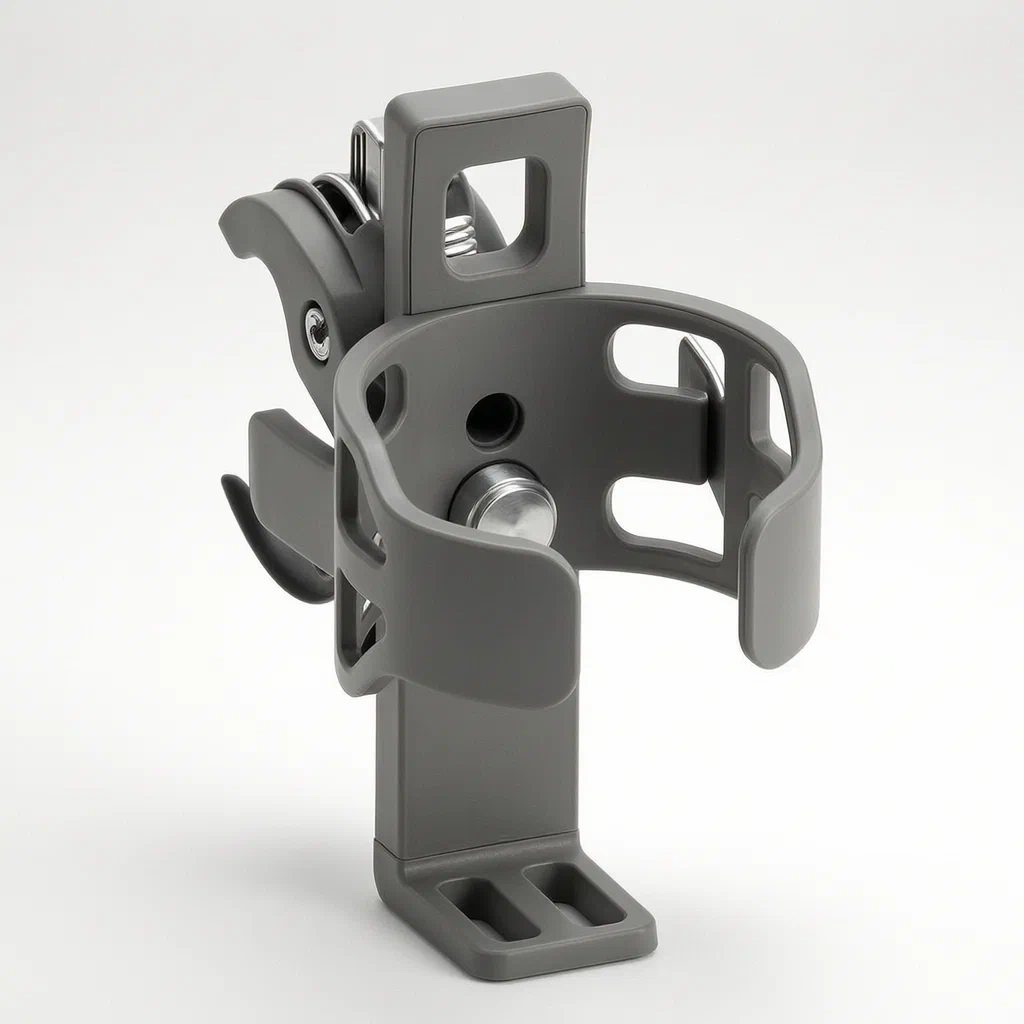
Standard adjustable cup holders often rely on friction joints that loosen over time or require complex ratchets to change angles. This design uses a simple mechanical indexing system: a coil spring pushes a latch block into one of several grooves arranged around the central pivot. This creates distinct, locked positions for the cup holder's orientation. When adjustment is needed, the user applies axial pressure to overcome the spring, rotating the holder freely until the latch drops into the next groove. It provides positive feedback and prevents accidental movement during travel, making it suitable for vehicles, boats, and outdoor equipment where vibration is common.
- China utility model - active
- No filings outside China
- Automotive & Marine Accessories
- Plastic/Metal seats, Coil Spring, C-Clip
Splat! What let you down?
🔒
Positive Locking
Latch block engages circumferential grooves to prevent rotation during vibration.
🔄
Quick Adjustment
Axial press overcomes spring force to release and rotate to the next position.
🥤
Universal Fit
C-shaped elastic clip accommodates various cup diameters without inserts.
🛠️
Flexible Mounting
Includes options for pivot arms with tightening screws for fixed installation.
Bring this product to market
- ✓ Patent review Patent family and legal status reviewed in the relevant jurisdictions.
- 2 Product brief · now How it works, uses and options written up
- 3 Prototype First samples for buyers to review
- 4 Pilot run Small first batch for launch customers
- 5 Volume production Repeat orders at scale
Buyer interest
– of 100 buyers needed to start prototyping
One click, no sign-up. Each vote is one real visitor, and products with the most interest go to prototyping first.
Build team: no members yet. Need a partner, co-funding or skills to build this? Join and we introduce the team once it forms.
Patent Rights & Team Participation
Before joining a development team, participants should ensure they have the necessary rights or authorization to participate in the project.
Participation is generally appropriate where:
- You own the relevant patent rights or have obtained permission or a license from the rights holder.
- The relevant patent rights have expired or have been legally invalidated in the jurisdictions where the planned activities will take place.
- The planned development, manufacturing, and commercialization activities have been independently assessed and do not infringe applicable patent rights in the relevant jurisdictions.
Important: Being located outside a country where a patent is protected does not automatically exempt you from patent infringement risks. Patent rights may apply based on where development, manufacturing, use, sale, or import activities take place.
IP2M does not grant any patent license or authorization through team participation. Joining a project does not provide permission to use, manufacture, or commercialize patented technology.
The problem
In many consumer products like bicycles, kayaks, cars, and camping gear, users need to hold drinks securely while moving. Fixed cup holders limit visibility or ergonomics if the drink needs to be moved out of the way. Friction-based adjustable holders often slip under vibration or temperature changes, leading to spills. Ratchet mechanisms provide locking but can be bulky, noisy, and prone to wear from debris. There is a need for a simple, robust mechanism that offers distinct, locked positions for orientation adjustment without complex internal gears or high-friction surfaces that degrade over time.
The solution
The patented device solves this by separating the rotational axis from the locking function using a spring-biased axial slide.
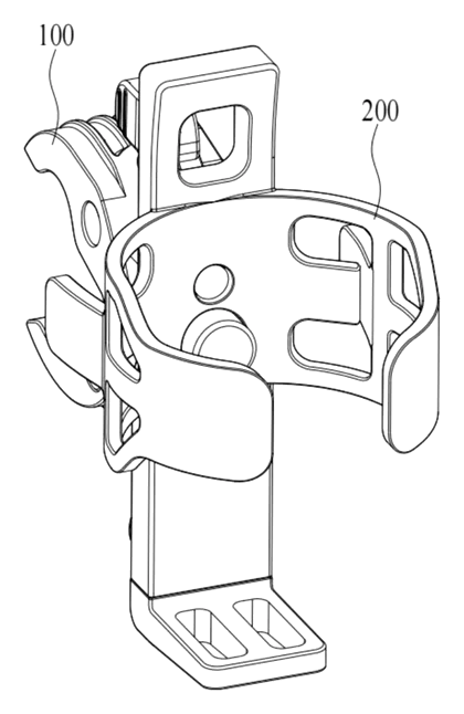
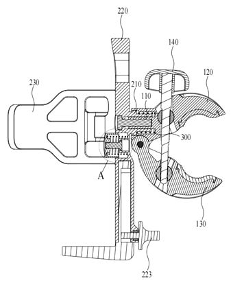
- Mounting Seat (100): Contains the first connecting part (110), which acts as the base interface. It features multiple clamping grooves (111) arranged at intervals around the central axis.
- Clamping Seat (200): Contains the second connecting part (210) which fits over or into the mounting seat. It holds the actual cup-holding structure.
- First Elastic Piece (300): A coil spring positioned between the two seats. It constantly pushes the Clamping Seat toward the “first position” (locked state).
- Latch Block (211): Located on the Clamping Seat. In the locked state, it sits inside one of the Clamping Grooves on the Mounting Seat, preventing relative rotation.
- Release Mechanism: To adjust, the user pushes the Clamping Seat axially against the spring force. This moves the Latch Block into an “avoidance groove” or clears the locking grooves, allowing free rotation. Releasing the pressure allows the spring to snap the Latch Block back into the next available groove, locking the new angle.
Who it is for
- Automotive Accessory Brands: Adding console-mounted or dash-mounted holders that need to fold flat when not in use.
- Marine Equipment Manufacturers: Boat rail mounts where spray and vibration require positive locking to prevent spills.
- Outdoor Gear Companies: Bicycle handlebar or kayak paddle holders where quick angle adjustment is needed for rider comfort.
- Furniture & Office Suppliers: Desk-side holders that allow users to swing a drink away from their workspace without loosening over time.
How it works
The main parts
| No. | Part | What it does |
|---|---|---|
| 100 | Mounting Seat | Base component; contains locking grooves (111). |
| 200 | Clamping Seat | Rotating component; carries the cup holder structure. |
| 300 | First Elastic Piece | Coil spring; biases the seats together for locking. |
| 211 | Latch Block | Protrusion on the Clamping Seat; engages grooves. |
| 111 | Clamping Grooves | Indentations on the Mounting Seat; define lock positions. |
| 210 | Second Connecting Part | Pivot interface between the two seats. |
| 400+ | Retainer/Clip | C-shaped elastic piece or plate to hold the cup itself. |
Operating Steps
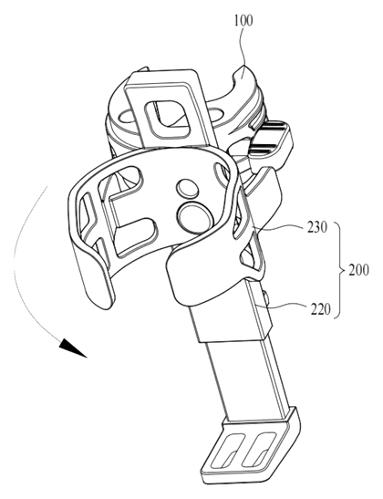
- Locked State: The spring (300) pushes the Clamping Seat (200) down onto the Mounting Seat (100). The Latch Block (211) sits firmly in one of the Clamping Grooves (111). Rotation is physically blocked.
- Unlocking: The user applies axial pressure to the Clamping Seat, compressing the spring. This lifts the Latch Block out of the groove (or into a wider avoidance channel).
- Rotation: With the latch disengaged, the user rotates the Clamping Seat to the desired angle.
- Re-Locking: The user releases the pressure. The spring expands, pushing the Latch Block into the next nearest Clamping Groove. The holder is now locked at the new angle.
Applications
Automotive Consoles
Drivers often need to move a drink out of the way for gear shifts or storage. This holder allows quick folding into a dashboard or center console recess, locking securely so it doesn’t rattle while driving.
Bicycle Handlebars
Cyclists may want a bottle angled forward for easy reach or backward to avoid wind resistance. The indexed locking ensures the bottle stays exactly where set, even over rough terrain, without slipping due to vibration.
Kayak and Canoe Rails
On watercraft, splashes and paddling motion create constant vibration. A friction joint might loosen, causing the cup to tilt and spill. The spring-loaded latch provides positive retention, keeping the cup upright regardless of boat movement.
Camping and Outdoor Furniture
Portable chairs or tables often have limited space. This mechanism allows the holder to be swung out of the way when not in use and snapped back into place when needed, offering durability against dust and dirt compared to open gears.
Where it is less suitable
- High-Speed Industrial Machinery: Vibration levels may exceed the spring’s holding capacity, requiring heavier-duty locking bolts.
- Single-Position Fixed Use: If the angle never needs changing, a simpler rigid mount is cheaper and lighter.
- Extreme Temperature Environments: Standard nylon or plastic springs may lose tension or become brittle; metal springs or specialized materials would be required.
Patent & Production
At a glance
| Patent number | CN216468203U (application CN202122828308) |
| Type | China utility model (实用新型) - protects product shape and structure |
| Original title | A Cup Holder (一种水杯支架) |
| Patent owner | Shenzhen Torras Technology Co ltd |
| Inventors | Chen Ling, Luo Kai |
| Filing date | 2021-11-17 |
| Grant date | 2022-05-10 |
| Status (China) | Active - In force in China until at most 2031-11-17 (if annual fees are paid) |
| Patent family | Public record shows Chinese filings only - no US, European, Japanese, PCT or other filings listed |
| Cited by | 3 later documents |
| Source | Google Patents (search for CN216468203U) |
What the claims cover, in plain language
Claim 1 defines a cup holder comprising a mounting seat, a clamping seat, and a first elastic piece. The two seats connect via a rotating fit. One seat has a latch block, and the other has multiple latching grooves arranged circumferentially around the connection point. A spring keeps the latch block engaged in a groove (locked position). Pushing the seats apart axially disengages the latch, allowing rotation. Releasing returns the latch to a groove.
Claims 2-5 specify the geometry: the connection uses a boss and a limiting post with a hole. The spring is a coil spring sleeved on the boss. The limiting post passes through the boss and is secured by a stopper (often threaded). An accommodating groove surrounds the post, housing the spring and latch mechanisms, with avoidance grooves aligned with the latching grooves to facilitate smooth disengagement.
Claims 6-9 describe the cup-holding element: a retainer member and a clamping member (often a C-shaped elastic clip) attached to the clamping seat. Some embodiments include a supporting plate with a sliding portion and a locking member (screw/bolt) to adjust the plate’s position. Another variant uses a second elastic member to push a locking plate against the cup.
Claim 10 details a specific mounting base option: two fixing arms hinged together, driven by a tightening screw with opposite thread directions on parallel movable shafts, allowing the arms to clamp tightly onto a tube or bar.
This is a simplified reading for orientation only. The legal scope is defined by the exact claim wording in the official Chinese document.
What this means for US production
This patent was filed in China and is currently active there. The public record shows no US or other foreign counterpart.
Two issues worth checking before tooling:
- Other patents may exist. Cup holders are a crowded product category, even if this latch mechanism looks unusual in the public record. Nuvo Enterprise Co., Ltd. and individual inventor Yu Fan have cited this patent in later applications (EP4428021A1 and WO2024221385A1 respectively). These citations suggest both are active in similar areas. Before launch, commission a freedom-to-operate (FTO) search covering existing US patents held by major accessory makers.
- Material Compliance. If used in automotive interiors, material flammability and VOC emissions must meet specific standards (e.g., FMVSS 302). For food-contact adjacent parts, FDA compliance for plastics may apply depending on final use.
Customization and manufacturing
What can be customized
| Area | Options |
|---|---|
| Locking Positions | Number and spacing of grooves (e.g., every 15°, 30°, or 45°). |
| Spring Rate | Adjusted for ease of use vs. vibration resistance. |
| Cup Clip Type | C-shaped elastic, dual-arm scissor, or rigid cradle. |
| Mounting Interface | Threaded bolt, snap-fit tab, or the hinged arm clamp (Claim 10). |
| Materials | Glass-filled nylon for strength, ABS for cost, stainless steel for marine. |
| Finish | Matte black, textured grip, or UV-stabilized coatings. |
Things to plan for (US market)
- FMVSS 302 - Flammability of interior materials, critical for automotive applications.
- REACH / Prop 65 - Chemical safety for plastics and metals, especially if sold in California.
- ASTM F963 - If marketed towards children’s toys or strollers, impact and small parts testing is required.
- Corrosion Resistance - For marine or outdoor use, salt spray testing (ASTM B117) is standard.
How a project runs
- Inquiry - Define target application (auto, bike, boat), load requirements, and aesthetic preferences.
- Design - CAD modeling of the latch/groove interface, spring selection, and clip geometry.
- Prototype - 3D printed functional samples to test latch feel and rotation smoothness.
- Pilot Run - Injection molded parts tested for fatigue, drop impact, and environmental exposure.
- Production - Mass molding, spring insertion, sub-assembly, and packaging.
Quantities & timeline
Tooling costs depend on the complexity of the latch mold (side-actions may be needed for undercuts). Assembly involves inserting springs and snapping components together. Send us your target quantity, material preference, and application context and we will reply with options.
Patent drawings
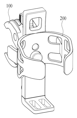
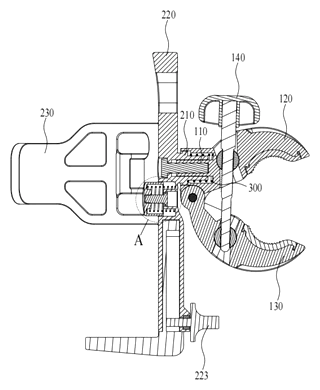
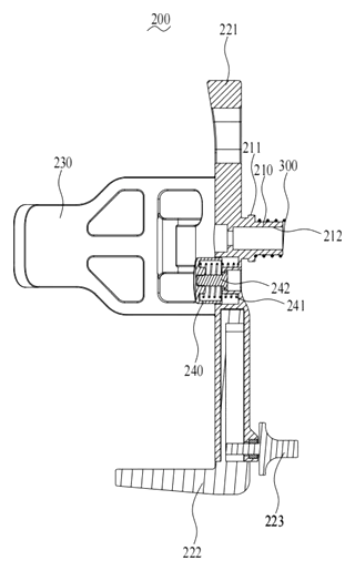
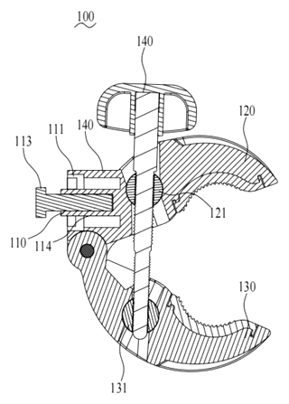
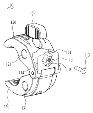
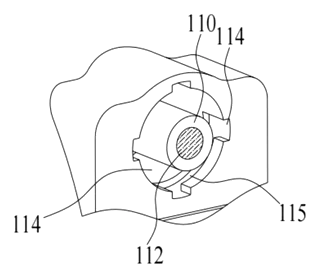
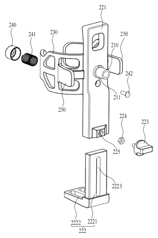
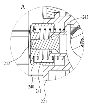
Drawings reproduced from the public patent document for reference.
Production notes
Tooling and process
Injection molding is likely the primary process for the plastic seats and clips. Aluminum extrusion or stamping may be used for metal mounting brackets. The coil spring is typically sourced externally or formed from wire stock.
Cost drivers
Weight typically affects shipping costs, particularly for bulk accessories. The number of molds increases tooling investment if different colorways or sizes are planned. Fastener count (screws/stoppers) adds assembly time and labor cost.
Prototyping path
Functional samples are usually created via 3D-printed parts to verify the latch action. Impact test samples help validate wall thickness before tooling. Machined frames serve as fixtures for assembly trials.
What we would change before tooling
We would optimize the draft angles on the grooves to ensure clean ejection. Wall thickness uniformity should be checked to prevent sink marks. Hinge boss dimensions need precise tolerance control to minimize play.
Common failure points
Cracking under impact is a risk if the plastic is too brittle. Spring fatigue could lead to weak locking over time. Bolts may loosen if not torqued correctly. UV degradation can embrittle external plastic parts.
Frequently asked questions
How does the locking mechanism work?
It uses a spring-loaded latch. A coil spring pushes the top part (clamping seat) down so a small block fits into a groove on the bottom part (mounting seat). This stops rotation. To change the angle, you push down to lift the block out of the groove, turn the holder, and let go. The spring snaps it into the next groove.
Is it difficult to adjust?
No. The spring tension is designed to be firm enough to hold against vibration but light enough for a user to press with one hand. The “click” into the next groove gives tactile feedback that it is locked.
What materials are used?
The patent describes plastic components (likely nylon or ABS) and a metal coil spring. The C-shaped clip is made of elastic material. Metal variants are possible for heavy-duty use. Specific grades are chosen based on the target environment (UV resistance for outdoors, heat resistance for cars).
Can it hold large bottles?
Yes. The C-shaped elastic clip adapts to different diameters. Alternatively, versions with adjustable support plates or locking members can accommodate larger containers. The size range is determined by the specific mold design.
Will it loosen over time?
Unlike friction joints, this mechanical latch does not rely on surface rubbing to stay tight. However, the spring can fatigue after thousands of cycles. We recommend testing spring life for your expected usage frequency. Better-grade steel springs resist fatigue better than low-cost alternatives.
Is it suitable for motorcycles?
Potentially, yes. Motorcycles experience high vibration. The positive lock helps prevent the holder from swinging loose. However, extreme impacts could cause cracking if the plastic is not reinforced (e.g., glass-filled nylon). Proper material selection is critical.
Can this design be made and sold in the US?
The patent is active in China, but the public record shows no US counterpart. Therefore, the patent itself does not restrict manufacturing or selling in the US. However, other companies may hold different US patents on similar cup holder technologies. We strongly recommend a freedom-to-operate check before mass production to avoid infringement risks.
Are you affiliated with the patent owner?
No. IP2M is an independent design and manufacturing service working from the public patent document.
Request a quote
Click Request a Quote below to see our email address - copy it, or open your email app with a ready-made message. Please mention patent CN216468203U in the subject.
Helpful details to include:
- Your company and channel (automotive, marine, cycling, furniture)
- Target environment (indoor, outdoor, high-vibration)
- Desired locking positions (number of angles)
- Cup size range
- Estimated quantity and target price
- Timeline - when you would like samples and the first shipment
You can also reach us at (332) 203-9997.
Page editor: Emily Zhang, Product Editor · IP2M
Last updated November 6, 2026. If something on this page looks wrong, email [email protected] and we will check it against the patent.
Interested in building this?
Tell us your target market, quantity and timeline. We reply with options for prototyping, small-batch runs or volume production.
Send your inquiry to
Please put CN216468203U in the subject line and tell us your company, country, estimated quantity and timeline.
Prefer to talk? Call (332) 203-9997.
More product-ready patents
All Sports & Recreation patents →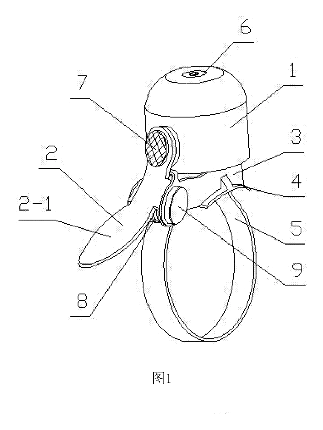
Sports & Recreation
Compact Torsion-Spring Bike Bell
Mini bike bell with a standard torsion spring and a rubber-floated dome - small size, clear tone, quick strap mount.
Patent CN205819384U
Sports & Recreation
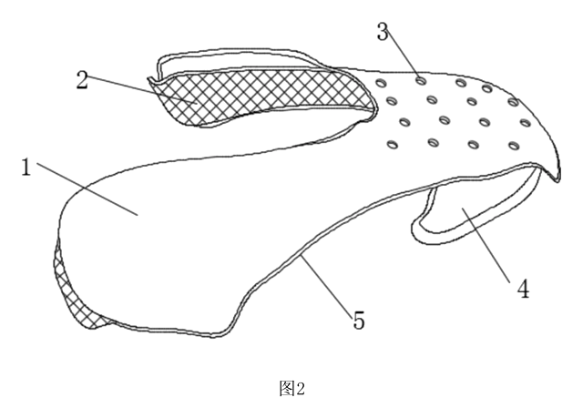
Padded Toe-Box Shield for Sneakers
Ventilated, silicone-lined toe-box insert that supports the front of a sneaker and cushions the toes.
Patent CN209473731U
Sports & Recreation
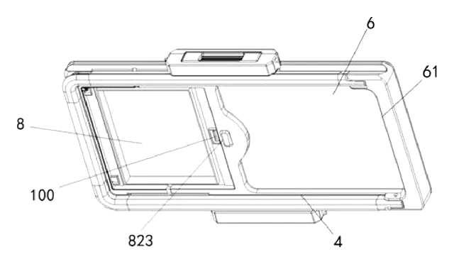
Reversible Fishing Seat-Box Lid with Backrest
Fishing seat-box lid that flips on removable hinge pins: cushion, backrest and storage on one face.
Patent CN208624426U
Sports & Recreation
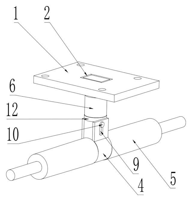
Swivel-Pin Skateboard Truck with Rubber Sleeve
Skateboard truck with a turning center pin, a tilting axle clamp and a rubber sleeve that centers it.
Patent CN216777880U
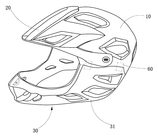
Sports & Recreation
Full-Face Bike Helmet with Magnetic Detachable Chin Bar
Full-face cycling helmet whose chin bar clips on and off with magnetic, latching side connectors.
Patent CN206630067U
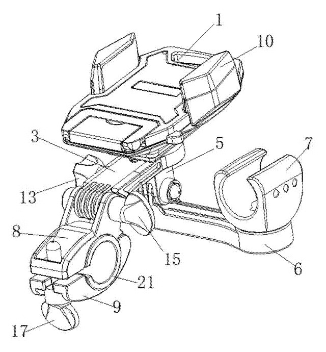
Sports & Recreation
Bike Phone Holder with Built-In Flashlight Clamp
Handlebar mount with a phone cradle on top and a flashlight clamp below, on one arm.
Patent CN206077485U
Browse by category
- Apparel & Accessories (44)
- Baby & Kids (28)
- Bags & Luggage (16)
- Bath & Personal Care (29)
- Car Accessories (23)
- Furniture, Bedding & Storage (23)
- Garden & Outdoor (31)
- Health & Wellness (13)
- Home, Kitchen & Cleaning (47)
- Lighting (22)
- Packaging & Containers (11)
- Pet Products (11)
- Phone & Camera Accessories (9)
- Retail Display (24)
- School, Office & Art (33)
- Sports & Recreation (43)
- Tools & Workshop (51)
- Toys & Games (21)
This page is based on the public patent document CN216468203U, assigned to Shenzhen Torras Technology Co ltd. IP2M is an independent manufacturing service and is not affiliated with, endorsed by or licensed by the patent owner. Images marked as concept renderings are illustrations, not photos of an existing product. Patent status information is provided for reference only and is not legal advice; confirm freedom to operate for your market before production. Full disclaimer.