
Patent CN216781775U
Updated November 8, 2026Drill Bit Case with a Foldable Handle and Secondary Locking Mechanism
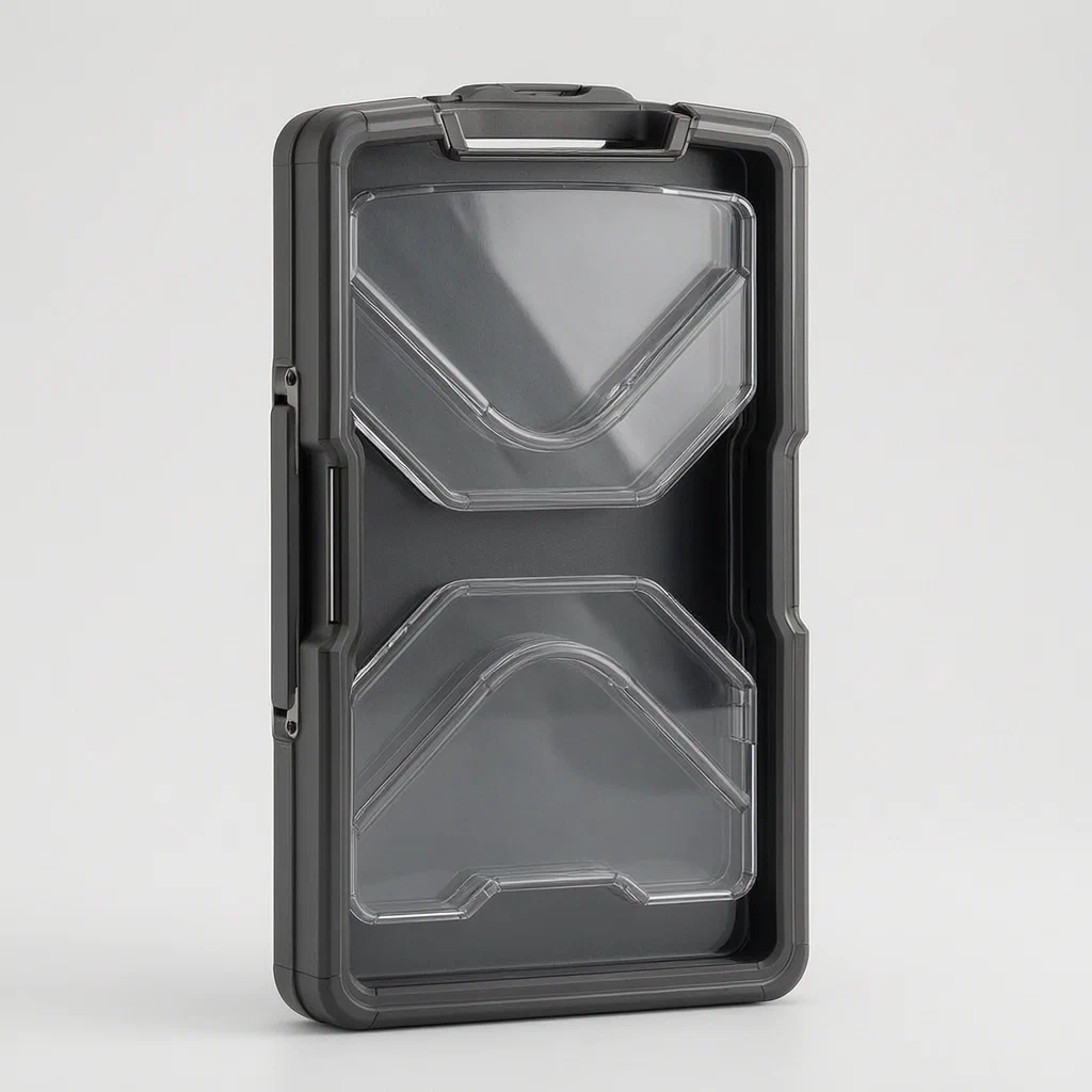
Standard tool cases often rely on a single latch that can vibrate open or be accidentally bumped. This drill bit box solves that by integrating the carry handle into the locking mechanism. The sliding latch holds the case closed, but when you fold the handle down flat against the body, the handle's connecting rods slide into place to block the latch. You cannot unlock the case unless you first stand the handle up. This visual and mechanical interlock ensures the case stays shut during transit, protecting both the tools and the user from exposed sharp drill bits.
- China utility model - in force
- No filings outside China
- Tool storage & packaging
- Plastic injection molded parts, sliding latch, foldable handle
Splat! What let you down?
🔒
Dual Locking System
The sliding latch closes the case; the folded handle blocks the latch from opening.
👁️
Visual Status Indicator
If the handle is down, the case is locked. If the handle is up, it can be opened.
📏
Transparent Organization
Internal baffles hold bits in size order, visible through clear top sections.
🛡️
Drop Protection
Prevents accidental unlatching during transport or impact.
Bring this product to market
- ✓ Patent review Patent family and legal status reviewed in the relevant jurisdictions.
- 2 Product brief · now How it works, uses and options written up
- 3 Prototype First samples for buyers to review
- 4 Pilot run Small first batch for launch customers
- 5 Volume production Repeat orders at scale
Buyer interest
– of 100 buyers needed to start prototyping
One click, no sign-up. Each vote is one real visitor, and products with the most interest go to prototyping first.
Build team: no members yet. Need a partner, co-funding or skills to build this? Join and we introduce the team once it forms.
Patent Rights & Team Participation
Before joining a development team, participants should ensure they have the necessary rights or authorization to participate in the project.
Participation is generally appropriate where:
- You own the relevant patent rights or have obtained permission or a license from the rights holder.
- The relevant patent rights have expired or have been legally invalidated in the jurisdictions where the planned activities will take place.
- The planned development, manufacturing, and commercialization activities have been independently assessed and do not infringe applicable patent rights in the relevant jurisdictions.
Important: Being located outside a country where a patent is protected does not automatically exempt you from patent infringement risks. Patent rights may apply based on where development, manufacturing, use, sale, or import activities take place.
IP2M does not grant any patent license or authorization through team participation. Joining a project does not provide permission to use, manufacture, or commercialize patented technology.
The problem
Small, high-value tools like twist drills require secure storage. In many plastic tool boxes, the primary latch is a simple slide or snap. During shipping or rough handling, vibrations or impacts can cause these latches to shift slightly, leading to accidental opening. If a drill bit case opens inside a toolbox or delivery package, the sharp bits can damage other tools, scratch surfaces, or pose a safety hazard to anyone reaching into the container. Additionally, organizing small bits of varying lengths requires dividers that don’t obscure visibility, making it hard to find the right size quickly without emptying the whole case.
The solution
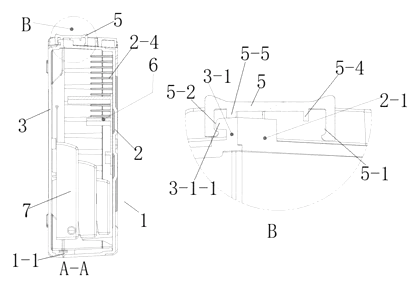
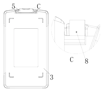
- The drill bit box (1) consists of an upper cover (2) and a lower cover (3). These two halves enclose the drill bits.
- A sliding lock catch (5) moves horizontally along the side of the box. It engages with protruding tabs on the covers to lock them together or disengage to allow opening.
- A foldable handle portion (4) is attached to the box via two connecting rods (first rod 4-1 and second rod 4-2). This handle can pivot between an upright carrying position and a folded-down stored position.
- The sliding lock catch features a specific third groove (5-3) designed to interact with the handle’s connecting rods.
- Mechanical Interlock: When the handle is folded down flat against the box body, the connecting rods move into a position that physically blocks the sliding lock catch from moving to the “unlock” position. The handle effectively jams the latch.
- To open the case, the user must first lift the handle to the upright position. This action retracts the connecting rods from the blocking position, freeing the sliding lock catch to slide open.
Who it is for
- Tool brands looking to differentiate their accessory kits with enhanced safety features that prevent customer complaints about loose bits.
- Amazon sellers who need robust packaging solutions that survive the rigors of third-party logistics without items spilling out.
- Hardware wholesalers supplying construction sites where tools are subjected to vibration, drops, and rough handling.
- DIY kit manufacturers creating beginner-friendly sets where ease of use and visible organization are key selling points.
How it works
The main parts
| No. | Part | What it does |
|---|---|---|
| 1 | Drill Bit Box | The overall assembly housing the tools. |
| 2, 3 | Upper/Lower Covers | Form the shell; one may have a transparent section. |
| 4 | Foldable Handle | Used for carrying; also acts as a secondary lock. |
| 4-1, 4-2 | Connecting Rods | Pivot points for the handle; engage with the latch. |
| 5 | Sliding Lock Catch | Primary mechanism to open/close the lid. |
| 5-3 | Third Groove | Interface on the latch that interacts with the handle rods. |
| 6 | Anti-Collision Baffle | Internal divider holding bits; often transparent. |
Operating Steps
- Closing the Case: Slide the lock catch (5) until it engages the protrusions on the covers, securing the box.
- Stowing the Handle: Fold the handle (4) down so it lies flat against the box surface. As it folds, the connecting rods (4-1, 4-2) align with the third groove (5-3) area on the latch.
- Secondary Locking: In this folded state, the rods physically obstruct the path of the sliding latch. The latch cannot be moved to the open position because the handle is in the way.
- Opening the Case: Lift the handle (4) to the vertical carrying position. This movement clears the obstruction from the latch’s track.
- Unlocking: Now slide the lock catch (5) to the open position to separate the upper and lower covers.
Applications
Construction Site Tool Kits
Workers drop toolboxes daily. The secondary lock ensures that even if the primary latch is jostled, the folded handle keeps the case shut, preventing drill bits from scattering onto steel beams or concrete floors.
Automotive Repair Shops
Mechanics work in tight spaces where bumping into shelves is common. This design prevents accidental spills of precision bits when a mechanic brushes past a shelf of organized cases.
E-commerce Fulfillment Centers
High-volume sorting systems involve tumbling bins and conveyor belts. The rigid interlock between the handle and latch reduces the risk of returns due to damaged or lost inventory caused by package failure.
Home DIY Workshops
For hobbyists, the transparent baffles allow quick identification of bit sizes (e.g., 1/8", 3/16") without opening the case. The easy-to-use handle lock simplifies access while maintaining security when stored on garage shelves.
Educational Tool Sets
Schools and vocational training centers need durable, safe containers. The visual cue—handle down means locked—helps students learn proper storage habits and reduces maintenance costs for broken latches.
Where it is less suitable
- Heavy Industrial Impact Zones - For extreme abuse, metal cases with cam locks are preferred over plastic interlocks.
- Very Large Tool Collections - This design is optimized for small-to-medium drill bit assortments; large socket sets require different volume ratios.
- Single-Use Packaging - The complexity of the molding and assembly makes it unsuitable for disposable or low-cost retail blisters.
Patent & Production
At a glance
| Patent number | CN216781775U (application CN202122505232) |
| Type | China utility model (实用新型) - protects product shape and structure |
| Original title | Drill bit box (一种钻头盒) |
| Patent owner | Shanghai Yingkai Tools Co ltd |
| Inventors | Wang Jianhua, Fang Lei |
| Filing date | 2021-10-19 |
| Grant date | 2022-06-21 |
| Status (China) | In force - valid until at most 2031-10-19, subject to annual fee payments |
| Patent family | Public record shows Chinese filings only - no US, European, Japanese, PCT or other filings listed |
| Cited by | 2 later documents |
| Source | Google Patents (search for CN216781775U) |
What the claims cover, in plain language
Claim 1 defines a drill bit box with an upper cover, lower cover, and a foldable handle. The key feature is a sliding lock catch with a specific groove. When the handle is folded down, it interacts with this groove to block the lock catch, providing a secondary lock. When the handle is up, the lock catch is free to slide.
Claims 2-7 detail the mechanical interface: the lock catch slides between the handle’s connecting rods. Protruding parts on the covers engage with grooves in the lock catch to achieve the primary lock/unlock function. The geometry of the rods and grooves is specified to ensure the interference fit when folded.
Claims 8-11 describe the internal organization. An anti-collision baffle part is included, which has a transparent bottom plate and multiple baffles to separate drill bits. This baffle snaps or clips into the inner walls of the box. The baffles may have stepped heights to accommodate different bit lengths.
This is a simplified reading for orientation only. The legal scope is defined by the exact claim wording in the official Chinese document.
What this means for US production
This patent was filed in China and is currently in force. Making or selling this specific design in China would require permission from the patent owner. However, the public record shows no US or other foreign counterpart to this patent. Therefore, this specific Chinese patent does not restrict manufacturing or sales in the United States.
Two points to settle early:
- Other patents may exist. Tool storage cases are a crowded field. While this specific “handle-as-secondary-lock” mechanism appears novel in the public record, general latch mechanisms and case structures may be covered by other US patents held by major tool brands (e.g., Stanley Black & Decker, Milwaukee, Klein Tools). A freedom-to-operate (FTO) review is recommended before committing to tooling.
- Material Safety. Since this product stores sharp metal tools, the plastic housing must withstand impact without shattering. Material selection is critical for liability reasons in the US market.
Customization and manufacturing
What can be customized
| Area | Options |
|---|---|
| Capacity | Number of drill bit slots (baffles) and bit length range |
| Handle Color | High-visibility colors (orange, yellow) vs standard black/grey |
| Latch Type | Sliding latch (as patented) or modified for push-button release |
| Transparency | Clear upper cover vs opaque; clear baffles vs colored |
| Mounting | Add hook holes for hanging on pegboards |
| Size | Mini (for small bits) to Standard (for full set) |
Things to plan for (US market)
- ASTM F963 - Consumer Product Safety Improvement Act (CPSIA) requirements for toys do not apply here, but general consumer product safety rules regarding sharp objects and containment do.
- Proposition 65 (California) - Requires warnings for chemicals known to cause cancer or reproductive harm. Ensure resins and colorants used in the plastic are compliant or provide necessary labeling.
- Impact Resistance - No specific federal regulation mandates drop tests for tool cases, but industry standards (often referenced in retailer contracts) require resistance to breaking under reasonable misuse.
How a project runs
- Design Validation - Confirm the latch/handle interference geometry matches your desired material tolerances.
- Mold Flow Analysis - Check for sink marks in thick sections (latch bosses) and fill balance in thin baffles.
- Prototype - CNC or 3D print samples to test the folding mechanism’s smoothness and locking strength.
- Tooling - Create injection molds for the upper/lower shells, handle, latch, and baffles.
- Production - Injection mold parts, assemble (snap-fit or screw), pack.
Quantities & timeline
Injection molding is the primary process. The cost is driven by the number of cavities (parts per shot) and mold complexity. The latch mechanism requires precise fitting to ensure the “secondary lock” works consistently. Send us your target capacity, color scheme, and estimated annual volume and we will reply with options.
Production notes
Tooling and process
The main bodies (upper and lower covers) likely require injection molding. The sliding latch and handle components also typically use injection molding. Assembly usually relies on snap-fits for the internal baffles and possibly ultrasonic welding or screws for the handle pivots. Thermoforming is generally not suitable for the structural rigidity required for the latch mechanism.
Cost drivers
Wall thickness directly affects material usage and cycle time, and is likely one of the main cost levers. The number of molds and cavities typically drives initial capital expenditure. Decoration (pad printing or in-mold labels) adds cost. Stacking volume during shipping influences logistics expenses.
Prototyping path
Start with a 3D-printed housing and latch to verify the handle-latch interference and the sliding action. A machined or 3D-printed handle is typically enough for the first fit check. Drop tests on a loaded box and repeated latch cycles should follow, to confirm the catch does not open under impact. Tooling would typically follow once the latch geometry is stable.
What we would change before tooling
We would adjust the wall thickness and joint design to prevent stress whitening at the corners where the handle pivots. We would also refine the hinge boss and pivot wear characteristics to ensure long-term durability. Ensuring uniform wall thickness helps avoid uneven shrinkage that could jam the sliding latch.
Common failure points
Cracking after drops is a primary concern for brittle plastics. Edge hardness and wear on the sliding latch tracks can lead to sticking. If the lid does not seal properly, dust ingress becomes an issue. Stress whitening at corners indicates insufficient radius or poor flow.
Patent drawings
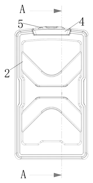
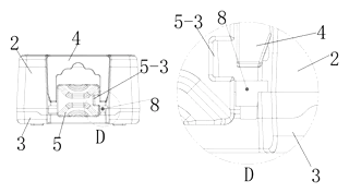
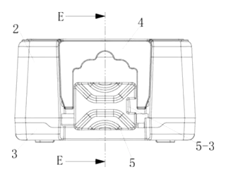
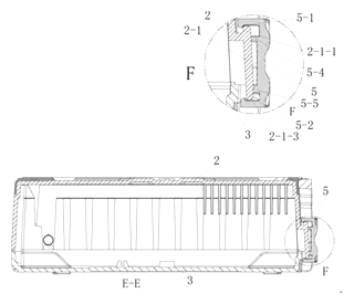
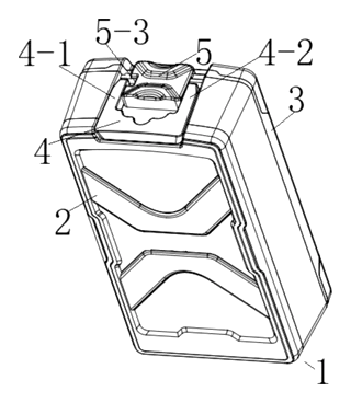
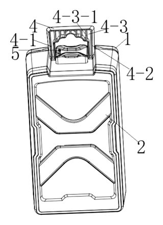
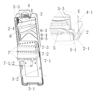
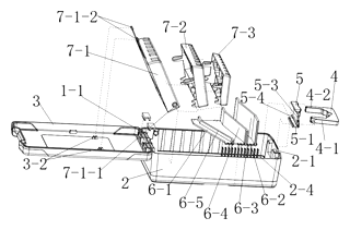
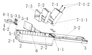
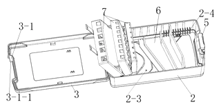
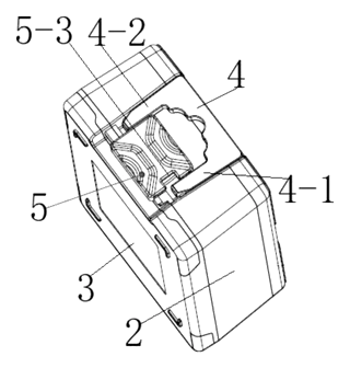
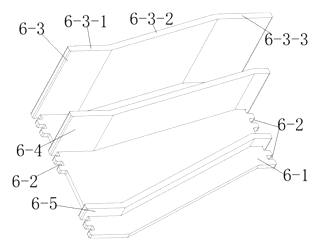
Drawings reproduced from the public patent document for reference.
Frequently asked questions
How does the secondary lock actually work?
It is a mechanical interference. The sliding latch has a groove. When you fold the handle down, the rods that attach the handle slide into that groove area, physically blocking the latch from moving. You cannot unlock the case until you lift the handle back up, which clears the block.
Can I customize the number of drill bits?
Yes. The internal baffles (part 6) can be adjusted in quantity and spacing. You can configure the case for small sets (e.g., 10 bits) or larger collections (e.g., 25+ bits) by changing the mold for the insert.
Is the plastic strong enough to protect sharp bits?
The patent describes an anti-collision baffle system. For production, we recommend high-impact polymers like ABS or Polypropylene (PP) with sufficient wall thickness. Drop tests are conducted during prototyping to confirm the case survives impacts without cracking or ejecting bits.
Does the transparent part fade over time?
The patent mentions a transparent bottom plate for the baffles. Depending on the material grade chosen (e.g., Polycarbonate vs. Acrylic), UV resistance varies. We can specify UV-stabilized resins if the cases will be stored in sun-exposed environments.
What is the difference between this and a standard snap-case?
Standard snap-cases rely solely on friction or a simple clip. This design uses a positive mechanical stop provided by the handle. This makes it significantly more resistant to accidental opening from vibration or minor impacts during shipping.
Can I add my brand logo?
Yes. Pad printing or laser etching can be applied to the upper cover or handle. In-mold decoration is also an option for higher volumes, though it increases tooling costs.
Can this design be made and sold in the US?
The patent was filed in China and is in force there. However, the public record shows no US counterpart to this patent. Therefore, this specific Chinese patent does not restrict manufacturing or sales in the United States. Note that other unrelated US patents may exist in the tool storage category, so a freedom-to-operate check is advisable.
Are you affiliated with the patent owner?
No. IP2M is an independent design and manufacturing service working from the public patent document.
Request a quote
Click Request a Quote below to see our email address - copy it, or open your email app with a ready-made message. Please mention patent CN216781775U in the subject.
Helpful details to include:
- Your company and channel (tool brand, Amazon seller, hardware distributor)
- Bit capacity (how many drill bits per case)
- Material preference (ABS, PP, etc.) and color codes
- Customization needs (logo, hook holes, label windows)
- Estimated quantity and target price
- Timeline - when you would like samples and the first shipment
You can also reach us at (332) 203-9997.
Page editor: Daniel Chen, Product Research Editor · IP2M
Last updated November 8, 2026. If something on this page looks wrong, email [email protected] and we will check it against the patent.
Interested in building this?
Tell us your target market, quantity and timeline. We reply with options for prototyping, small-batch runs or volume production.
Send your inquiry to
Please put CN216781775U in the subject line and tell us your company, country, estimated quantity and timeline.
Prefer to talk? Call (332) 203-9997.
More product-ready patents
All Packaging & Containers patents →
Packaging & Containers
Rigid Shell Container with Removable Silicone Liner
Cup or food box with a rigid outer shell and a removable, leak-tight silicone liner.
Patent CN212638395U
Packaging & Containers
Child-Resistant Paperboard Medicine Box with Three-Point Opening
Paperboard medicine box that opens only when press points on three sides are pushed together.
Patent CN107117365B
Packaging & Containers
Tape-Free Reusable Shipping Box with Zigzag Interlocking Flaps
Reusable carton closed without tape: zigzag flaps interlock, tabs tuck in, a U-clip locks the lid.
Patent CN207242262U
Packaging & Containers
Hinge Device for Folding Containers with Integrated Twistlock Hole
Folding container hinge with a built-in twistlock hole and observation port.
Patent CN113460518B
Packaging & Containers
Cylindrical Plastic Bottle Cap with Built-In Soup Ladle
Plastic bottle cap storing a soup ladle inside, with a flip-top lid and inner sealing closure.
Patent CN106144192B
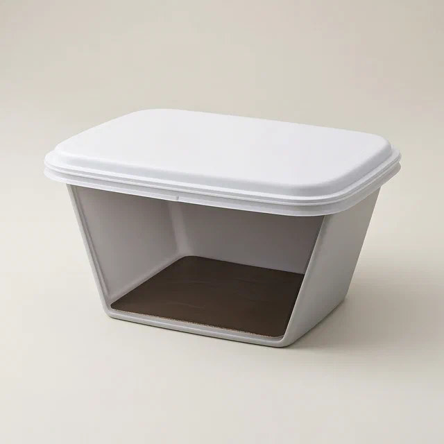
Packaging & Containers
Insulated Food Packaging Box with Detachable Liner and Self-Heating Cavity
Detachable insulated food box with a sealed cavity for a self-heating sheet and a temperature sticker.
Patent CN108372980B
Browse by category
- Apparel & Accessories (50)
- Baby & Kids (29)
- Bags & Luggage (17)
- Bath & Personal Care (33)
- Car Accessories (26)
- Furniture, Bedding & Storage (25)
- Garden & Outdoor (34)
- Health & Wellness (14)
- Home, Kitchen & Cleaning (52)
- Lighting (24)
- Packaging & Containers (13)
- Pet Products (12)
- Phone & Camera Accessories (9)
- Retail Display (26)
- School, Office & Art (38)
- Sports & Recreation (48)
- Tools & Workshop (56)
- Toys & Games (23)
This page is based on the public patent document CN216781775U, assigned to Shanghai Yingkai Tools Co ltd. IP2M is an independent manufacturing service and is not affiliated with, endorsed by or licensed by the patent owner. Images marked as concept renderings are illustrations, not photos of an existing product. Patent status information is provided for reference only and is not legal advice; confirm freedom to operate for your market before production. Full disclaimer.