
Patent CN216884066U
Updated October 27, 2026Replaceable Electric Fabric Cutting Knife Head with Alloy Inserts
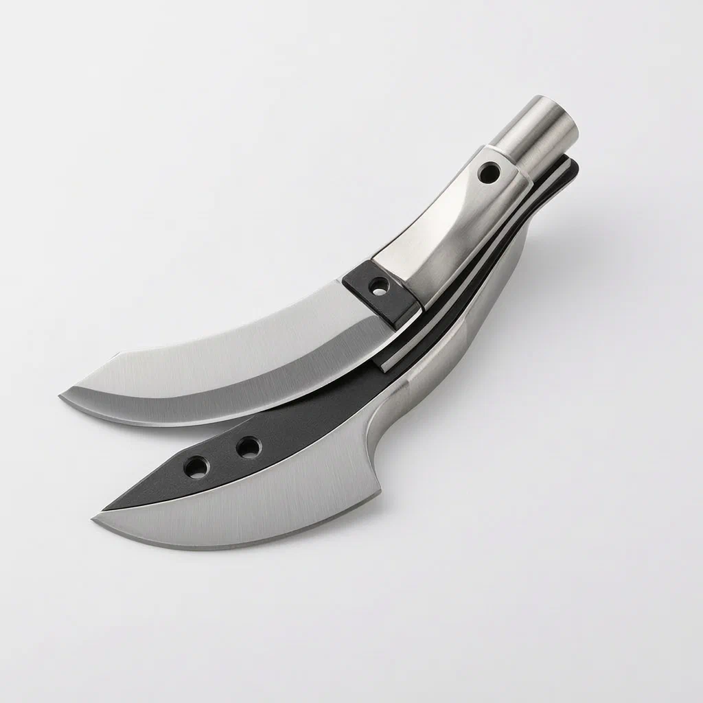
Fabric cutting tools wear out fast when metal rubs directly against metal and plain steel edges dull under continuous use. This replaceable electric cutting knife head addresses both issues. The upper and lower knives are single-piece components, each carrying an alloy insert pressed into a dedicated groove along the cutting edge. As the blades run against each other, the two alloys interact continuously to maintain sharpness. Between the upper and lower assembling portions inside the knife head shell, a wear-resistant gasket prevents direct friction between the moving parts. The lower knife features a bent connecting portion that offsets the lower assembling portion, setting it at a 3-degree angle to the lower knife part so the blades meet with a slight tilt suited for tailoring cloth. Both blades are heat treated to a hardness of HRC 55, and their cutting edges sit at a 45-degree angle to the vertical plane. The entire knife head shell detaches from the machine body, letting operators swap a worn head for a fresh one without disassembling the motor housing.
- China utility model - in force
- No filings outside China
- Knives & Cutters
- Alloy-inserted blades, HRC 55 heat treatment, detachable head
Splat! What let you down?
🔩
Alloy blade inserts
Upper and lower blades carry alloy pieces in dedicated grooves, maintaining edge sharpness as they run together.
🛡️
Wear-resistant gasket
A gasket between the upper and lower assembling parts prevents direct friction inside the knife head shell.
🔄
Detachable knife head
The front end of the machine body connects to the knife head shell detachably for quick replacement.
📐
Angled cutting geometry
Blade edges sit at 45 degrees to the vertical plane, and the lower blade tilts 3 degrees for clean fabric cuts.
Bring this product to market
- ✓ Patent vetted China-only family and legal status checked
- 2 Product brief · now How it works, uses and options written up
- 3 Prototype First samples for buyers to review
- 4 Pilot run Small first batch for launch customers
- 5 Volume production Repeat orders at scale
Buyer interest
– of 100 buyers needed to start prototyping
One click, no sign-up. Each vote is one real visitor, and products with the most interest go to prototyping first.
Build team: no members yet. Need a partner, co-funding or skills to build this? Join and we introduce the team once it forms.
The problem
Electric fabric cutters used in garment workshops and upholstery shops rely on reciprocating upper and lower blades to shear through multiple layers of cloth. Over time, the cutting edges dull, and the pivot area where the two blades cross wears down from constant metal-on-metal friction. When the pivot wears, the blades lose their alignment, causing the fabric to fold or bunch instead of shearing cleanly. Replacing the blades on many conventional models requires dismantling the motor housing or sending the tool for repair, resulting in downtime on the cutting table. Furthermore, standard steel edges require frequent sharpening or replacement when processing abrasive textiles like denim or canvas.
The solution
This design introduces a complete, detachable knife head that replaces the worn unit in one step, leaving the motor body untouched.
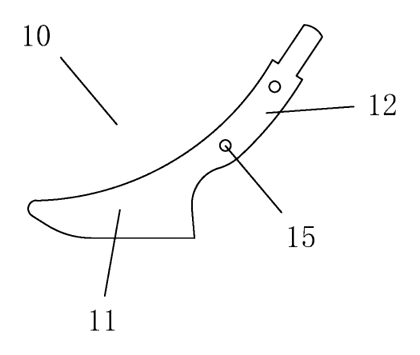
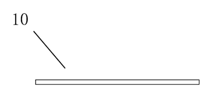
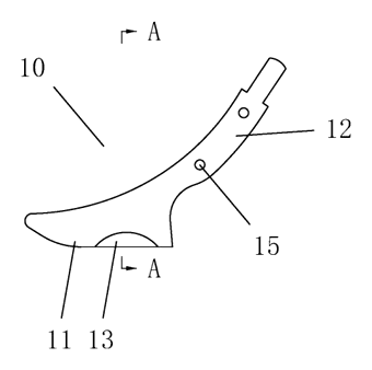
- The upper knife (1) is formed as one piece with an upper knife part (11) and an upper assembling part (12) located at its rear upper section. An upper groove (13) near the lower blade holds an inserted upper alloy member (14).
- The lower knife (2) is also integrally formed, consisting of a lower knife part (21), a connecting part (22) and a lower assembling part (23). A lower groove (24) near the upper blade receives a lower alloy piece (25).
- A wear-resistant gasket (3) is installed inside the knife head shell (4) directly between the upper assembling part (12) and the lower assembling part (23), preventing direct friction between them.
- The two knives are hinged together inside the shell via an upper hinge hole (15) and a matching lower hinge hole (26) secured by hinge columns.
- The connecting part (22) is bent so the lower assembling part (23) sits obliquely, forming a 3-degree angle with the lower knife part (21). The bend creates an included angle of about 49 degrees (±1 degree) with the vertical plane.
- The cutting edges of both knives form a 45-degree angle with the vertical plane, and both blades undergo heat treatment to a hardness of HRC 55.
Who it is for
- Garment factory equipment buyers who need to minimize downtime on cutting tables by swapping heads rather than repairing internal mechanisms.
- Upholstery and home textile manufacturers cutting heavy or abrasive fabrics where standard steel edges dull quickly.
- Power tool brands looking to add a professional-grade, user-replaceable fabric cutter to their product line.
- Wholesalers of sewing and tailoring supplies supplying independent tailors and small workshops that require reliable daily cutting tools.
How it works
The main parts
| No. | Part | What it does |
|---|---|---|
| 1 | Upper knife | Integrally formed blade with upper knife part (11) and upper assembling part (12). |
| 13, 14 | Upper groove and alloy member | Groove on the blade edge holding the inserted alloy piece. |
| 15 | Upper hinge hole | Pivot point for the upper knife. |
| 2 | Lower knife | Integrally formed blade with lower knife part (21), connecting part (22) and lower assembling part (23). |
| 24, 25 | Lower groove and alloy piece | Groove on the blade edge holding the inserted alloy piece. |
| 26 | Lower hinge hole | Pivot point matching the upper hinge hole. |
| 3 | Wear-resistant gasket | Sits between the assembling parts to prevent direct friction. |
| 4 | Knife head shell | Houses the knives and gasket; attaches detachably to the machine body. |
| 5 | Machine body | Contains the driving motor component and circuit. |
| 6 | Key switch | Electrically connected to the driving circuit to operate the tool. |
Operating steps
- Attach the knife head - connect the knife head shell (4) to the front end of the machine body (5).
- Activate the tool - press the key switch (6) to power the driving motor component inside the machine body.
- Cut the fabric - the motor drives the upper knife (1) and lower knife (2) to perform opposite cutting movements. The 3-degree tilt allows the blades to shear the cloth cleanly.
- Replace when worn - detach the knife head shell from the machine body and install a new pre-assembled head.
Applications
Garment manufacturing
Tailors and factory workers cutting multiple layers of woven or knit fabrics use this tool to maintain straight lines. The alloy inserts keep the edge sharp through long production runs, reducing the frequency of blade changes.
Upholstery and furniture
Workers cutting heavy materials like canvas, denim or synthetic leather experience rapid wear on standard blades. The wear-resistant gasket protects the pivot mechanism from the high friction generated by thick textiles.
Home sewing and quilting
Independent sewists working on large projects benefit from the detachable head. When the blades eventually dull after extended use, replacing the entire shell is faster than attempting to sharpen small reciprocating blades.
Automotive interior trimming
Technicians cutting fabric, foam-backed cloth or thin vinyl for car seats and headliners need precise shearing. The 45-degree edge angle and 3-degree blade tilt provide the geometry required for controlled cuts without snagging.
Where it is less suitable
- Rigid materials - this cutter is designed for cloth and flexible textiles; it is not intended for cutting hard plastics, sheet metal or wood.
- Single-layer paper crafting - the heavy-duty alloy blades and motorized action are built for fabric shearing, making the tool excessive for light craft paper tasks.
Frequently asked questions
Why are there alloy pieces inserted into the blades?
The patent describes an upper alloy member inserted into a groove on the upper blade and a lower alloy piece embedded in a groove on the lower blade. According to the patent, these alloys constantly run against each other during use, which keeps the blade sharp and improves wear resistance compared to plain steel edges.
What does the wear-resistant gasket do?
It is installed inside the knife head shell, positioned directly between the upper assembling part and the lower assembling part. According to the patent, it prevents direct friction between these two moving sections, further improving the wear resistance and service life of the product.
How do I replace the knife head?
The front end of the machine body is detachably connected to the knife head shell. When the blades wear out, you disconnect the shell from the motor body and attach a new pre-assembled knife head, avoiding the need to open the motor housing.
What are the blade angles?
The cutting edges of both the upper and lower knives form a 45-degree angle with the vertical plane. Additionally, the connecting part of the lower knife is bent so the lower assembling part sits at a 3-degree angle to the lower knife part, allowing the blades to contact each other at that 3-degree inclination for better fabric tailoring.
How hard are the blades?
The patent specifies that both the upper knife and the lower knife undergo heat treatment, with a hardness requirement of HRC 55.
Can the tool cut materials other than fabric?
The patent describes the tool specifically for tailoring cloth. The blade geometry, motor drive and 3-degree tilt are designed for shearing textiles. Suitability for other flexible materials is set in design / confirmed on prototypes.
Can this design be made and sold in the US?
The patent was filed only in China and is in force in China until at most 2031-07-21 (if annual fees are paid). It does not restrict making or selling the design in the US. However, electric fabric cutters may be covered by other US patents - see Patent & Production - so we recommend a freedom-to-operate check before volume production.
Are you affiliated with the patent owner?
No. IP2M is an independent design and manufacturing service working from the public patent document.
Request a quote
Click Request a Quote below to see our email address - copy it, or open your email app with a ready-made message. Please mention patent CN216884066U in the subject.
Helpful details to include:
- Your company and channel (power tool brand, garment equipment supplier, upholstery wholesaler)
- Target fabrics and cutting thickness requirements
- Motor specifications (voltage, desired speed)
- Shell interface dimensions if adapting to an existing machine body
- Estimated quantity and target price
- Timeline - when you would like samples and the first shipment
You can also reach us at (332) 203-9997.
Explore this product
Interested in building this?
Tell us your target market, quantity and timeline. We reply with options for prototyping, small-batch runs or volume production.
Send your inquiry to
Please put CN216884066U in the subject line and tell us your company, country, estimated quantity and timeline.
Prefer to talk? Call (332) 203-9997.
More product-ready patents
All Tools & Workshop patents →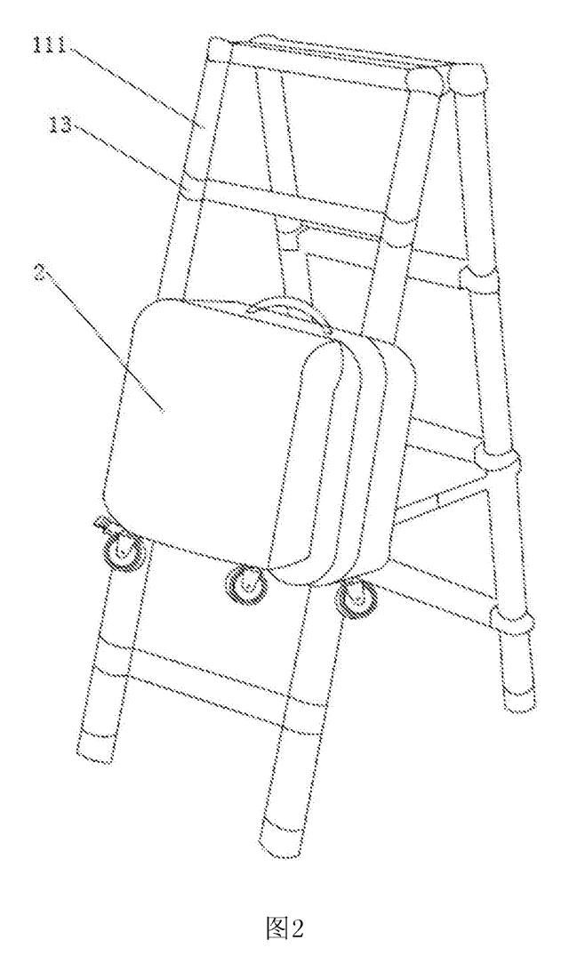
Tools & Workshop
Rolling Tool Box with Telescoping Step Ladder
Telescoping A-frame ladder with an attached rolling tool box that slides to your working height.
Patent CN206290197U
Tools & Workshop
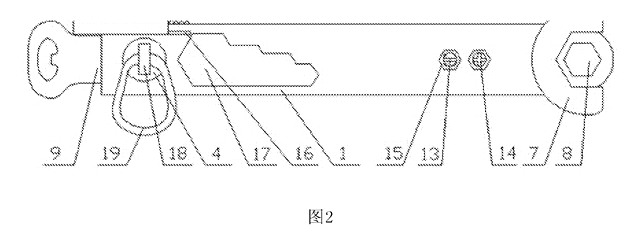
Folding 3-Handle Wrench Multi-Tool
Folding three-handle wrench multi-tool with magnetic screwdriver bits, saw, file and bottle opener.
Patent CN205290875U
Tools & Workshop
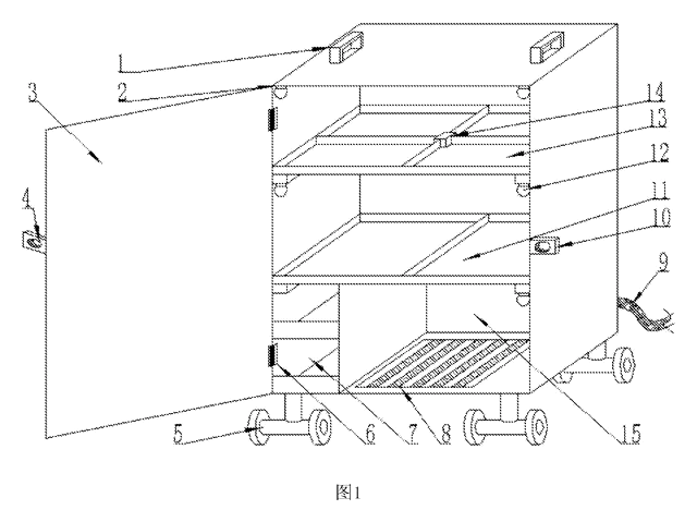
Rolling Auto-Repair Tool Cabinet with Built-In Lights
Lockable rolling tool cabinet for car repair with interior lights, a lubricant tray, parts drawers and a tool bay.
Patent CN205989314U
Tools & Workshop
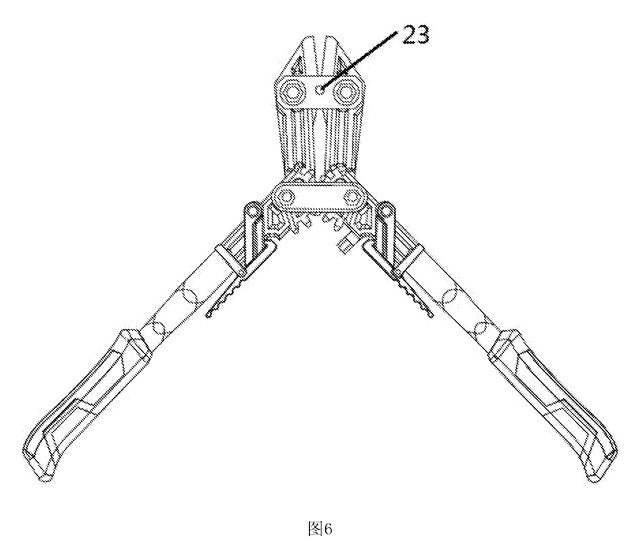
Wide-Opening Folding Bolt Cutter
Bolt cutter with linked, gear-meshing handles that open up to 190° and fold in half for storage.
Patent CN207206226U
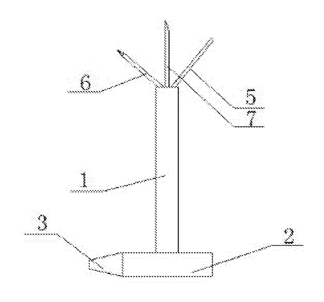
Tools & Workshop
Nail-Holding Hammer with Fold-Out Drivers
Hammer with a nail-holding T-slot in the head and fold-out drivers stored in the handle.
Patent CN205254927U
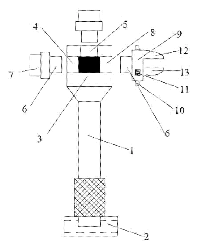
Tools & Workshop
Modular Wrench with Screw-On Heads
Wrench handle with a three-way threaded hub for screw-on adjustable and hex heads, plus a pipe sleeve.
Patent CN206216564U
Browse by category
- Apparel & Accessories (22)
- Baby & Kids (16)
- Bags & Luggage (9)
- Bath & Personal Care (16)
- Car Accessories (10)
- Furniture, Bedding & Storage (12)
- Garden & Outdoor (18)
- Health & Wellness (8)
- Home, Kitchen & Cleaning (24)
- Lighting (12)
- Packaging & Containers (6)
- Pet Products (6)
- Phone & Camera Accessories (4)
- Retail Display (13)
- School, Office & Art (19)
- Sports & Recreation (25)
- Tools & Workshop (27)
- Toys & Games (12)
This page is based on the public patent document CN216884066U, assigned to Zhongshan Tianhong Motor Manufactrure Co ltd. IP2M is an independent manufacturing service and is not affiliated with, endorsed by or licensed by the patent owner. Images marked as concept renderings are illustrations, not photos of an existing product. Patent status information is provided for reference only and is not legal advice; confirm freedom to operate for your market before production. Full disclaimer.