At a glance
| Patent number | CN216884066U (application CN202121673191) |
| Type | China utility model (实用新型) - protects product shape and structure |
| Original title | Removable electronic sword tool bit and electronic sword of tailorring (一种可更换的电动裁剪刀刀头及电动裁剪刀) |
| Patent owner | Zhongshan Tianhong Motor Manufactrure Co ltd |
| Inventors | Mai Detian |
| Filing date | 2021-07-21 |
| Grant date | 2022-07-05 |
| Status (China) | In force in China until at most 2031-07-21 (if annual fees are paid) |
| Patent family | Chinese filings only - no US, European, Japanese, PCT or other filings listed |
| Cited by | 2 later documents |
| Source | Google Patents (search for CN216884066U) |
What the claims cover, in plain language
Claim 1 - a replaceable electric cutting knife head with a knife head shell, an upper knife and a lower knife mounted on the shell. The upper knife has an integrally formed upper knife part and upper assembling part at its rear upper section. The lower knife is integrally formed with a lower knife part, a connecting part and a lower assembling part at its rear upper section. Both assembling parts are installed in the shell while the knife parts protrude outside. A wear-resistant gasket is placed between the upper and lower assembling parts inside the shell.
Claim 2 - an upper groove on the lower end of the upper knife part holds an upper alloy member; a lower groove on the upper end of the lower knife part holds a lower alloy piece. Claim 3 - the upper assembling part has an upper hinge hole and the lower assembling part has a matching lower hinge hole; the upper assembling part, gasket and lower assembling part are hinged in the shell by hinge columns. Claim 4 - the connecting part is bent so the lower assembling part is inclined at a 3-degree angle to the lower knife part, and the connecting part forms an included angle of 49 degrees ±1 degree with the vertical plane. Claim 5 - the cutting edges of both knives form a 45-degree angle with the vertical plane. Claim 6 - both knives are heat treated to a hardness requirement of HRC 55. Claim 7 - an electric cutting knife comprising a machine body with a key switch, where the front end of the body is detachably connected to the knife head shell. Inside the body are a driving motor component for moving the knives oppositely and a driving circuit connected to the key switch.
This is a simplified reading for orientation only. The legal scope is defined by the exact claim wording in the official Chinese document.
What this means for US production
This patent was filed only in China and is currently in force in China until at most 2031-07-21 (if annual fees are paid). It has no US or other foreign counterpart. However, because it remains active in China, making or selling this exact knife head design in China needs the owner’s permission.
Two points to settle early:
- Other patents may exist. Electric fabric cutters and reciprocating shear mechanisms are covered by various international patents held by major power tool companies. Because no foreign patents citing this document were identified, we still strongly recommend a freedom-to-operate (FTO) review focused on the detachable shell mechanism, alloy-inserted blade geometry and hinge arrangement before launching in the US.
- Blade safety and guarding. Exposed reciprocating blades present pinch and laceration hazards. The blade guard design, trigger lock and overall housing must be engineered to meet US safety expectations for handheld power tools.
Customization and manufacturing
What can be customized
| Area | Options |
|---|---|
| Alloy material | Tungsten carbide or other hard alloys for the upper and lower inserts, chosen based on target fabrics |
| Gasket material | Wear-resistant polymers or composite materials, to be confirmed in design |
| Shell construction | Plastic or metal housing, shaped to fit specific machine body interfaces |
| Blade geometry | Angles set in design / confirmed on prototypes around the patented 45-degree and 3-degree baseline |
| Motor specifications | Voltage, RPM and torque matched to the intended cutting capacity |
| Switch type | Key switch, paddle switch or lock-on slider depending on user preference |
Things to plan for (US market)
- UL 60745 / CSA standards - safety requirements for hand-held motor-operated electric tools, covering electrical insulation, thermal limits and mechanical guarding.
- FCC Part 15 - if the driving circuit includes electronic speed control or wireless features, electromagnetic interference limits apply.
- California Proposition 65 - materials used in the plastic shell, alloy inserts and wiring must be screened for regulated substances.
How a project runs
- Inquiry - define the target fabrics, motor voltage, shell interface and order volume.
- Design - engineer the knife head shell, select alloy grades, dimension the gasket and finalize the hinge column layout.
- Prototype - produce sample heads to verify the 3-degree blade tilt, cutting action and gasket wear over repeated cycles.
- Pilot run - assemble a batch for functional testing, heat-treatment verification (HRC 55) and safety compliance checks.
- Production - blank, bend and mill the knives, insert the alloys, mold the shells, stamp the gaskets and assemble the final units.
Quantities & timeline
Manufacturing requires stamping and milling dies for the integral upper and lower knives, precision tooling for inserting the alloy members into the blade grooves, injection molds for the knife head shell, and heat-treatment furnaces calibrated for HRC 55 hardness. Certification tests for handheld power tools add time to the initial schedule. Send us your target fabric types, motor specs, quantity and compliance requirements and we will reply with options.
Patent drawings
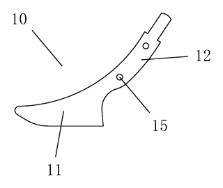
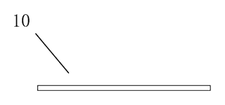
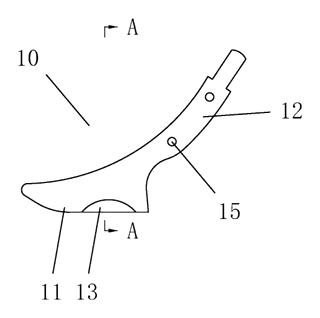
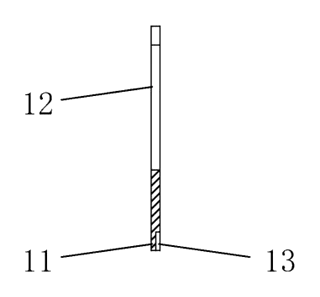
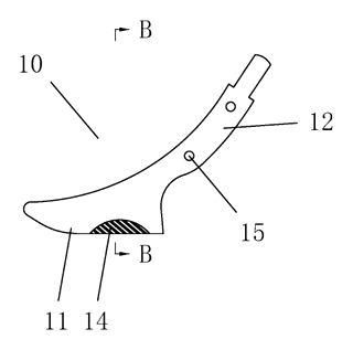
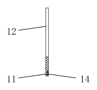
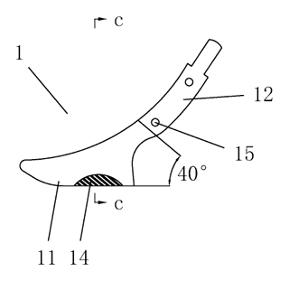
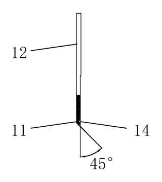
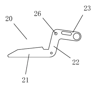
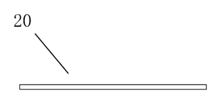
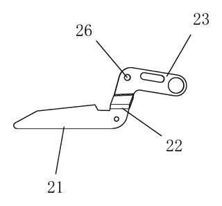
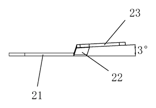
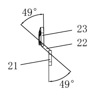
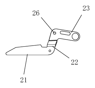
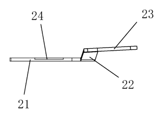
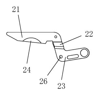
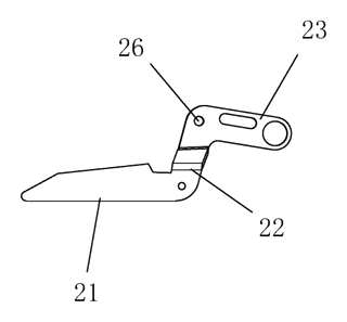
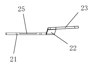
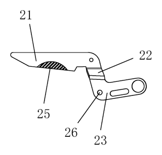
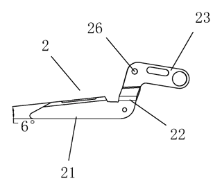
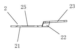
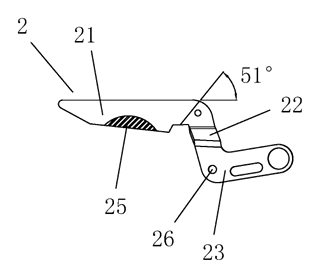
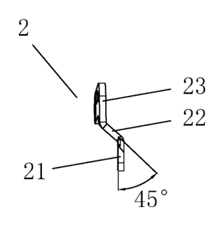
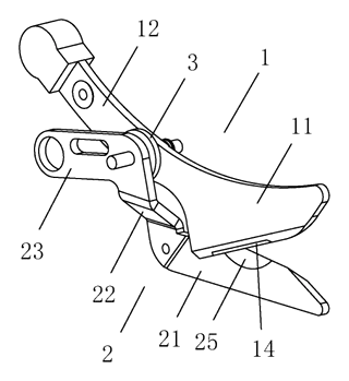
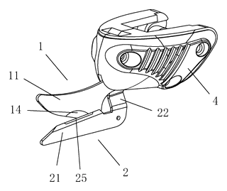
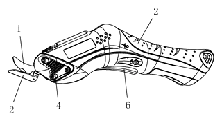
Drawings reproduced from the public patent document for reference.