Patent Information & Production OptionsAutomotive Foot Massage Device with Adjustable Cover Plate · Patent CN217566713U

Patent CN217566713U: bibliographic data, legal status, family, a plain-language reading of the claims, plus customization, US compliance points and how a manufacturing project runs.

At a glance

Patent numberCN217566713U (application CN202220189260)
TypeChina utility model (实用新型) - protects product shape and structure
Original titleFoot massage device and automobile seat (足部按摩装置及汽车座椅)
Patent ownerAnwen Automobile Technology Tianjin Co ltd
InventorsZhang Haitao
Filing date2022-01-24
Grant date2022-10-14
Status (China)In force - valid until at most 2032-01-24, provided annual fees are paid
Patent familyChinese filings only - no US, European, Japanese, PCT or other filings listed
Cited by4 later documents
SourceGoogle Patents (search for CN217566713U)

What the claims cover, in plain language

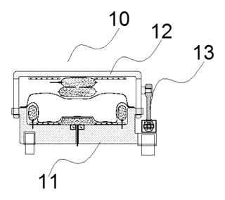
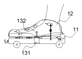
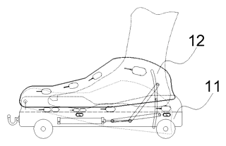
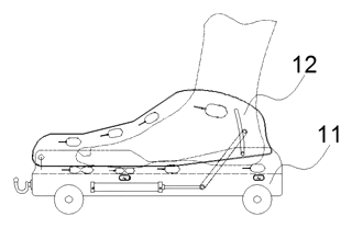
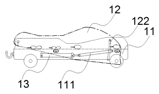
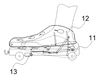
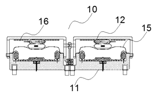
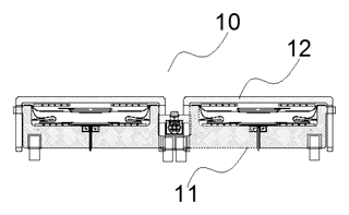
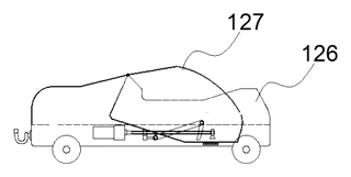
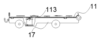
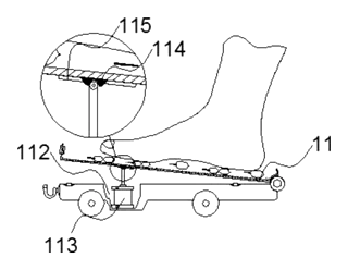
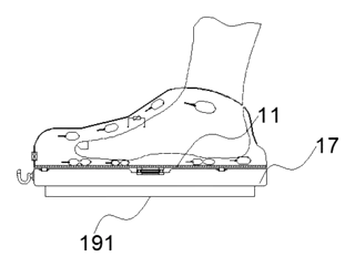
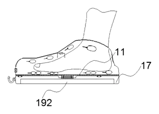
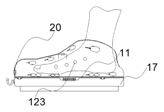
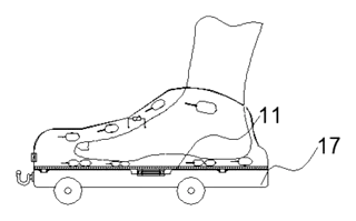
Claim 1 - a foot massage device comprising a carrier substrate (11) and a cover plate (12). A driving mechanism (13) moves the cover plate relative to the substrate, allowing it to approach or recede from the base. This adjustability adapts the device to vehicle-mounted space limits.

Specific Structural Variations:

  • Sliding Fit: Side edges of the cover plate and substrate form an up-down sliding relationship.
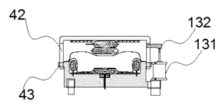
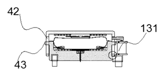
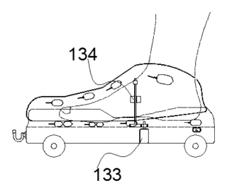
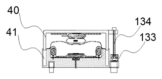
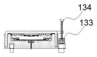
  • Ball Screw Drive: Includes a driving motor (133), ball screw nut pair, and fitting ring (134) on the cover plate.
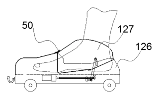
  • Rotational Connection: One end of the cover plate rotates relative to the substrate; the other end is free.
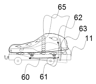
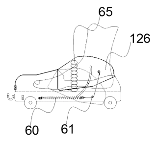
  • Elastic Cable System: Uses an elastic retractable body (60), guide column (61), and cable rope (63) bypassing hooking points (62) to pull the cover plate.
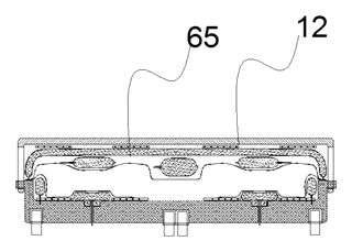
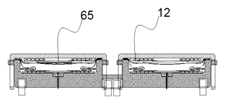
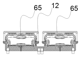
  • Airbag Support: A top support airbag group (65) assists in maintaining the height of the cover plate.
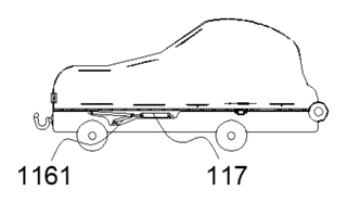
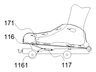
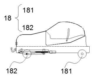
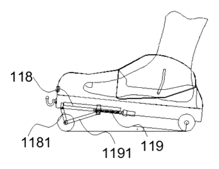
  • Support Rods: Combinations of support grooves, rods, and cylinders (117, 119) allow for angular adjustment of the substrate relative to a swivel base.

This is a simplified reading for orientation only. The legal scope is defined by the exact claim wording in the official Chinese document.

What this means for US production

This patent was filed only in China and is currently in force. Making or selling this specific adjustable structure in China requires the owner’s permission. In the US, there is no direct counterpart to this patent, but similar mechanisms may be covered by other intellectual property.

Two points to settle early:

  • Other patents may exist. Automotive seat comfort systems are heavily patented globally, including adjustable lumbar and footrest mechanisms. A freedom-to-operate (FTO) review is essential to check for US patents covering similar “adjustable height” or “ball screw driven cover” technologies before tooling.
  • Integration Standards. The device must interface with standard automotive seat frames. Dimensions and mounting points vary by OEM platform, requiring custom adaptation layers.

Customization and manufacturing

What can be customized

AreaOptions
Drive TypeBall screw, elastic cable, or airbag-assisted lift
Range of MotionVertical travel distance based on seat gap availability
Motor SpecVoltage, RPM, and noise level for vibration motor
MaterialsHigh-strength plastics or lightweight alloys for substrate/plate
Control InterfaceWired switch, wireless remote, or CAN bus integration
Surface FinishLeather wrapping, fabric covering, or anti-slip texture

Things to plan for (US market)

  • FMVSS / NHTSA: While this is an accessory, any modification to the seat structure must not compromise safety standards regarding crashworthiness and restraint systems.
  • Electrical Safety: Motors and wiring must meet automotive-grade insulation and fire resistance standards (e.g., UL or equivalent automotive specs).
  • Noise/Vibration/Harshness (NVH): The mechanism must operate quietly to avoid interfering with cabin acoustic targets.
  • Durability Testing: Components undergo cycle testing for thousands of adjustments to simulate vehicle lifespan.

How a project runs

  1. Inquiry - Define seat platform, available space, and desired massage intensity.
  2. Design - Select drive mechanism (screw vs. cable), size the motor, and design mounting brackets.
  3. Prototype - Build functional samples for fit-check and NVH evaluation.
  4. Pilot run - Validate durability through cycle tests and environmental exposure.
  5. Production - Injection molding for plastic parts, machining for metal guides, and assembly with electronics.

Quantities & timeline

Molds for the substrate and cover plate are required. Precision components like ball screws or guide columns may be sourced from existing suppliers. Development time focuses on integrating the control logic and ensuring silent operation. Send us your target vehicle platform, space constraints, and quantity requirements and we will reply with options.

Patent drawings
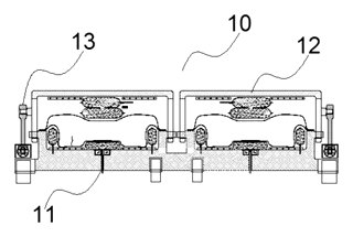
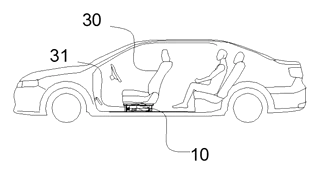
Automotive Foot Massage Device with Adjustable Cover Plate - Patent Fig. 1
Fig. 1 - Overview of the foot massage device.
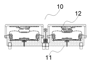
Automotive Foot Massage Device with Adjustable Cover Plate - Patent Fig. 2
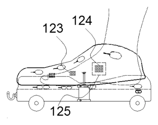
Fig. 2 - Exploded view of the assembly.
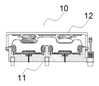
Automotive Foot Massage Device with Adjustable Cover Plate - Patent Fig. 3
Fig. 3 - Cross-section of the sliding mechanism.
Automotive Foot Massage Device with Adjustable Cover Plate - Patent Fig. 4
Fig. 4 - Detail of the limiting cylinder.
Automotive Foot Massage Device with Adjustable Cover Plate - Patent Fig. 5
Fig. 5 - Ball screw drive arrangement.
Automotive Foot Massage Device with Adjustable Cover Plate - Patent Fig. 6
Fig. 6 - Rotational connection variant.
Automotive Foot Massage Device with Adjustable Cover Plate - Patent Fig. 7
Fig. 7 - Elastic cable retraction system.
Automotive Foot Massage Device with Adjustable Cover Plate - Patent Fig. 8
Fig. 8 - Airbag support structure.
Automotive Foot Massage Device with Adjustable Cover Plate - Patent Fig. 9
Fig. 9 - Support rod linkage.
Automotive Foot Massage Device with Adjustable Cover Plate - Patent Fig. 10
Fig. 10 - Second support groove detail.
Automotive Foot Massage Device with Adjustable Cover Plate - Patent Fig. 11
Fig. 11 - Swivel base plate configuration.
Automotive Foot Massage Device with Adjustable Cover Plate - Patent Fig. 12
Fig. 12 - Third support cylinder mechanism.
Automotive Foot Massage Device with Adjustable Cover Plate - Patent Fig. 13
Fig. 13 - Sliding rail alternative.
Automotive Foot Massage Device with Adjustable Cover Plate - Patent Fig. 14
Fig. 14 - Mounting interface details.
Automotive Foot Massage Device with Adjustable Cover Plate - Patent Fig. 15
Fig. 15 - Internal component layout.
Automotive Foot Massage Device with Adjustable Cover Plate - Patent Fig. 16
Fig. 16 - Electrical connection points.
Automotive Foot Massage Device with Adjustable Cover Plate - Patent Fig. 17
Fig. 17 - Protective casing design.
Automotive Foot Massage Device with Adjustable Cover Plate - Patent Fig. 18
Fig. 18 - Ventilation openings.
Automotive Foot Massage Device with Adjustable Cover Plate - Patent Fig. 19
Fig. 19 - Alternative drive gear.
Automotive Foot Massage Device with Adjustable Cover Plate - Patent Fig. 20
Fig. 20 - Sensor placement.
Automotive Foot Massage Device with Adjustable Cover Plate - Patent Fig. 21
Fig. 21 - Feedback loop diagram.
Automotive Foot Massage Device with Adjustable Cover Plate - Patent Fig. 22
Fig. 22 - Material cross-section.
Automotive Foot Massage Device with Adjustable Cover Plate - Patent Fig. 23
Fig. 23 - Assembly sequence step 1.
Automotive Foot Massage Device with Adjustable Cover Plate - Patent Fig. 24
Fig. 24 - Assembly sequence step 2.
Automotive Foot Massage Device with Adjustable Cover Plate - Patent Fig. 25
Fig. 25 - Assembly sequence step 3.
Automotive Foot Massage Device with Adjustable Cover Plate - Patent Fig. 26
Fig. 26 - Final assembled state.
Automotive Foot Massage Device with Adjustable Cover Plate - Patent Fig. 27
Fig. 27 - Retracted state comparison.
Automotive Foot Massage Device with Adjustable Cover Plate - Patent Fig. 28
Fig. 28 - Extended state comparison.
Automotive Foot Massage Device with Adjustable Cover Plate - Patent Fig. 29
Fig. 29 - User interaction flow.
Automotive Foot Massage Device with Adjustable Cover Plate - Patent Fig. 30
Fig. 30 - Failure mode analysis.
Automotive Foot Massage Device with Adjustable Cover Plate - Patent Fig. 31
Fig. 31 - Thermal dissipation path.
Automotive Foot Massage Device with Adjustable Cover Plate - Patent Fig. 32
Fig. 32 - Acoustic dampening layer.
Automotive Foot Massage Device with Adjustable Cover Plate - Patent Fig. 33
Fig. 33 - Modular attachment clips.
Automotive Foot Massage Device with Adjustable Cover Plate - Patent Fig. 34
Fig. 34 - Wiring harness routing.
Automotive Foot Massage Device with Adjustable Cover Plate - Patent Fig. 35
Fig. 35 - Control module box.
Automotive Foot Massage Device with Adjustable Cover Plate - Patent Fig. 36
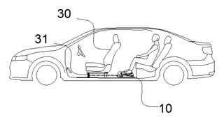
Fig. 36 - Full system integration.

Drawings reproduced from the public patent document for reference.
🔥 Popularity – views

Bring this product to market

  1. ✓ Patent vetted China-only family and legal status checked
  2. 2 Product brief · now How it works, uses and options written up
  3. 3 Prototype First samples for buyers to review
  4. 4 Pilot run Small first batch for launch customers
  5. 5 Volume production Repeat orders at scale

Buyer interest

– of 100 buyers needed to start prototyping

or request a quote Share to speed it up:

One click, no sign-up. Each vote is one real visitor, and products with the most interest go to prototyping first.

Build team: no members yet. Need a partner, co-funding or skills to build this? Join and we introduce the team once it forms.

Join the build team

Want to develop this product with others? Tell us what you can bring. When the team has enough people, we introduce the members to each other by email.

I can help with (pick any)

Letters only. The team list on this page shows your country and the first 5 letters of your name (e.g. "Micha**"); leave the name blank to appear as "Anonymous".

No money is collected on this site. IP2M does not hold or manage funds, and pledges are non-binding. We email you a link to confirm; only confirmed members are introduced to each other. See our privacy policy.

Interested in building this?

Tell us your target market, quantity and timeline. We reply with options for prototyping, small-batch runs or volume production.

All Health & Wellness patents →

This page is based on the public patent document CN217566713U, assigned to Anwen Automobile Technology Tianjin Co ltd. IP2M is an independent manufacturing service and is not affiliated with, endorsed by or licensed by the patent owner. Images marked as concept renderings are illustrations, not photos of an existing product. Patent status information is provided for reference only and is not legal advice; confirm freedom to operate for your market before production. Full disclaimer.