
Patent CN220930728U
Updated November 2, 2026One-Touch Locking Ball Head Mount for Cameras and Equipment
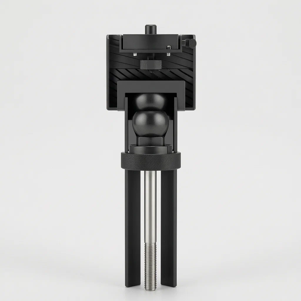
Traditional ball heads require separate actions to attach the camera and lock the tilt. This design merges them into one intuitive motion: turn the knob clockwise to screw the mount onto your device and simultaneously push the internal rod to clamp the ball. Turn it counter-clockwise to release the clamp before unscrewing. It’s a streamlined solution for photographers, videographers, and industrial users who need quick, reliable adjustments without fumbling with multiple levers.
- China utility model - withdrawn
- No filings outside China
- Camera & Device Mounts
- Mechanical torque coupling, spherical cavity lock
Splat! What let you down?
🔄
Single Knob Control
One rotation locks the ball and secures the attached device simultaneously.
⚙️
Torque Transmission
Internal spring and clutch mechanism transfers force from the knob to the locking rod.
🔒
Positive Clamping
The connecting rod extends to press the ball head firmly against the housing opening.
🛠️
Modular Design
Split knob halves and standardized threading allow for easy manufacturing and repair.
Bring this product to market
- ✓ Patent vetted China-only family and legal status checked
- 2 Product brief · now How it works, uses and options written up
- 3 Prototype First samples for buyers to review
- 4 Pilot run Small first batch for launch customers
- 5 Volume production Repeat orders at scale
Buyer interest
– of 100 buyers needed to start prototyping
One click, no sign-up. Each vote is one real visitor, and products with the most interest go to prototyping first.
Build team: no members yet. Need a partner, co-funding or skills to build this? Join and we introduce the team once it forms.
The problem
Standard ball heads often require two distinct steps to use effectively: first, securing the camera or device to the base using a standard thread, and second, tightening a separate lever or knob to lock the ball joint so the angle holds. This separation can lead to user error—forgetting to lock the ball after attaching a heavy lens, causing the equipment to droop—or inconvenience during rapid field changes. Furthermore, multi-lever designs increase the physical size and complexity of the mount, making it less compact for travel-oriented photography or tight-space industrial applications. Users frequently struggle with the coordination required to tighten the attachment while maintaining the desired angle, leading to misalignment or stripped threads if over-tightened independently.
The solution
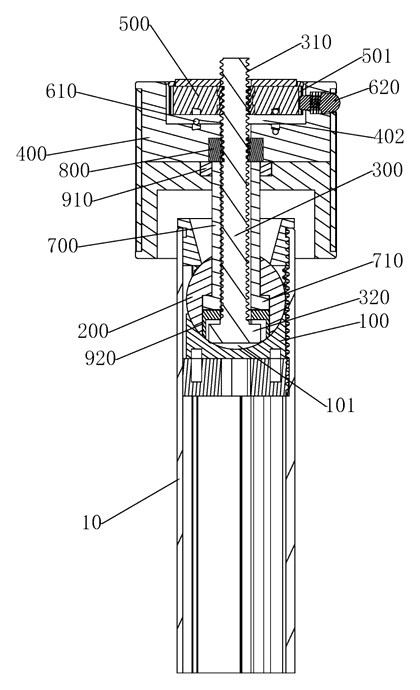
- Integrated Mechanism: The design combines the attachment screw and the ball lock into a single control interface. A connecting rod passes through the ball head, with one end protruding from the top surface and the other forming a threaded column.
- Torque Coupling: A knob piece is screwed onto the threaded column. Between the knob and the column lies a torque transmission mechanism, typically involving a spring plate and a clutch-like engagement.
- Two-Stage Action: When the knob is rotated in the first direction (e.g., clockwise), the torque mechanism initially turns the threaded column to screw the mount onto the external device. Once resistance builds up (indicating the device is seated), continued rotation causes the knob to drive the connecting rod outward relative to the ball.
- Locking the Ball: As the connecting rod extends, its tip presses against the inner edge of the spherical cavity in the seat body. This pressure clamps the ball head rigidly, preventing any movement.
- Release: Rotating the knob in the opposite direction retracts the connecting rod, releasing the clamp on the ball before the threads disengage from the device.
Who it is for
- Photography Gear Brands: Companies looking to differentiate their tripod heads by offering a simplified, single-knob user experience that reduces setup time for consumers.
- Industrial Sensor Integrators: Manufacturers needing robust, compact mounts for cameras, LiDAR units, or inspection sensors where vibration resistance and quick adjustment are critical.
- Action Camera Accessory Makers: Brands producing small, lightweight mounts for helmets, bikes, or drones where space is limited and multiple levers would be cumbersome.
- DIY Electronics Enthusiasts: Hobbyists building custom rigs who want a mechanical solution that avoids electronic latches or complex gearing, relying instead on simple, durable metal and plastic parts.
How it works
The main parts
| No. | Part | What it does |
|---|---|---|
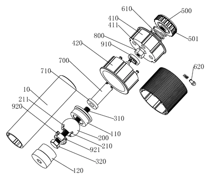
| 100 | Seat Body | Contains the spherical cavity with an opening; mounts to the tripod or stand. |
| 200 | Ball Head | Rotates within the seat body; houses the connecting rod. |
| 300 | Connecting Rod | Slides through the ball; extends to lock the ball, retracts to release. |
| 310 | Threaded Column | End of the rod; screws into the device being mounted. |
| 400 | Knob Piece | User interface; rotates to drive the locking and attachment process. |
| 500 | Bearing Plate | Internal component that interacts with the torque mechanism. |
| 610 | Spring Plate | Provides elastic force for the torque transmission. |
| 620 | Clutch Piece | Engages/disengages based on torque levels to switch from screwing to locking. |
| 700 | Sleeve | Guides the connecting rod through the ball head. |
| 800 | Nut | Fixed inside the knob to mate with the threaded column. |
Operating Steps
- Attach Device: Place the mount against the camera’s threaded hole. Rotate the knob clockwise. The torque mechanism turns the threaded column, screwing the mount onto the device.
- Engage Lock: Continue rotating clockwise. Once the device is snug, the resistance triggers the torque limit. The knob now pushes the connecting rod outward via the internal sleeve.
- Clamp Ball: The extended rod presses the ball head against the edge of the seat body’s opening, locking the angle in place.
- Adjust Angle: To change the angle, rotate the knob counter-clockwise. The rod retracts, releasing the clamp. Adjust the ball freely.
- Remove Device: Continue counter-clockwise rotation until the threads fully disengage from the device.
Applications
DSLR and Mirrorless Tripods
Photographers benefit from the speed of attaching lenses and locking the frame with one hand. The single knob reduces the chance of forgetting to lock the ball, which can cause expensive gear to sag or fall when bumped.
Security and Inspection Cameras
Installers often work at heights or in confined spaces. A one-touch mount allows them to aim the camera precisely and secure it without juggling multiple tools or levers, ensuring the unit stays fixed despite wind or vibration.
Action and Drone Mounts
For small, lightweight devices like GoPros or drone gimbals, space is premium. Eliminating a secondary locking lever makes the mount significantly more compact and aerodynamic, while still providing a positive mechanical lock against the chassis.
Industrial Robotic Arms
In automation setups, end-effectors or vision systems need frequent repositioning. This mechanism allows operators to quickly swap tools or adjust angles with a single rotational input, streamlining production line changes.
Where it is less suitable
- High-Vibration Heavy Machinery: While robust, the reliance on a single point of contact for locking may not suffice for extreme industrial vibrations compared to bolt-through flanges.
- Ultra-Low Cost Consumer Toys: The precision required for the torque transmission and clutch mechanism adds manufacturing complexity compared to simple friction-based ball joints.
- Quick-Release Shoe Systems: Photographers using Arca-Swiss or Manfrotto plates prefer slide-on mechanisms rather than screw-in attachments for rapid switching.
Frequently asked questions
How does the “one-touch” locking actually work?
It uses a torque-sensitive mechanism. When you turn the knob, it first acts as a normal screw to attach your camera or device. Once the device is snug, further rotation triggers an internal shift that pushes a rod outwards. This rod presses the ball head against the housing, locking the angle. You don’t need a second lever.
Is it stronger than a standard lever-lock ball head?
The locking force depends on the material strength and the spring tension designed into the torque mechanism. For typical camera loads, it provides a very rigid hold because the locking is done by direct mechanical compression of the ball against the socket, rather than just friction from a lever. However, it is generally suited for lighter to medium loads compared to massive industrial bolt-down systems.
Can I use it with any tripod?
Yes, provided the tripod has a standard mounting thread (usually 1/4" or 3/8"). The bottom of the seat body attaches to the tripod legs, and the top of the connecting rod attaches to your camera or device.
What happens if I overtighten it?
The torque transmission mechanism is designed to slip or reach a hard stop once the locking rod is fully extended. This prevents damage to the threads or the ball head itself. Continued rotation usually results in the knob spinning freely or hitting a mechanical limit, protecting the internal components.
Are the internal parts replaceable?
The design features a split knob (upper and lower halves) and accessible internal sleeves. While not intended for daily user repair, the modular nature allows for easier servicing or part replacement during manufacturing QC or specialized maintenance.
What materials are used?
The patent describes a metallic construction. Typically, the seat and ball are made from aluminum alloys or stainless steel for durability, while the knob and internal guides might use high-strength engineering plastics like POM or Nylon to reduce weight and friction.
Can this design be made and sold in the US?
The patent was filed only in China and has been abandoned (withdrawn) as of March 2026. Therefore, it does not restrict the design in the US. However, because ball head mechanisms are heavily patented globally, we recommend a freedom-to-operate check to ensure no other active US patents cover this specific torque-transfer method.
Are you affiliated with the patent owner?
No. IP2M is an independent design and manufacturing service working from the public patent document.
Request a quote
Click Request a Quote below to see our email address - copy it, or open your email app with a ready-made message. Please mention patent CN220930728U in the subject.
Helpful details to include:
- Your company and channel (camera accessory brand, industrial integrator, action cam maker)
- Load requirements (weight of the device to be mounted)
- Thread specifications (1/4", 3/8", or custom)
- Material preferences (aluminum, steel, plastic mix)
- Estimated quantity and target price
- Timeline - when you would like samples and the first shipment
You can also reach us at (332) 203-9997.
Explore this product
Interested in building this?
Tell us your target market, quantity and timeline. We reply with options for prototyping, small-batch runs or volume production.
Send your inquiry to
Please put CN220930728U in the subject line and tell us your company, country, estimated quantity and timeline.
Prefer to talk? Call (332) 203-9997.
More product-ready patents
All Phone & Camera Accessories patents →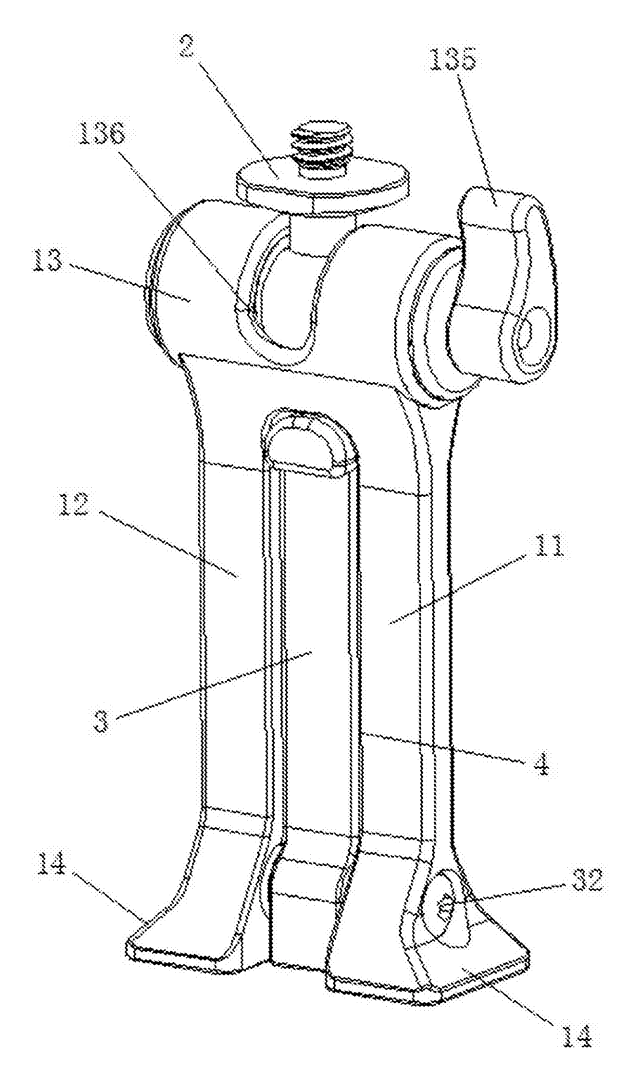
Phone & Camera Accessories
Phone Clip Mount with Fold-Out Stand Leg
Phone clamp adapter with a ball-joint top, a dovetail base for tripod clamps and a fold-out desk leg.
Patent CN207394276U
Stands & Mounts
Manual Quick-Release Connector for Camera Equipment
Quick-release camera mount using a rotating driver and spring-loaded locking grooves.
Patent CN215294199U
Phone & Camera Accessories
Extendable Support Leg and Monopod with Single-Knob Locking
Three-section monopod leg locked and released from one top knob via a transmission rod.
Patent CN113090903B
Phone & Camera Accessories
Remote-Controlled Outdoor Photography Tripod with Movable Lens Mount
Motorized tripod with a remote-driven camera seat and a sliding multi-lens mount.
Patent CN118328254B
Phone & Camera Accessories
Foldable Multifunctional Mobile Phone Clip with Rotating Support Feet
Foldable phone clip with rotating tripod-compatible feet and 1/4-inch screw mounts.
Patent CN207112268U
Bags & Cases
Trolley Case with Integrated Child Seat and Side Steps
Travel suitcase featuring a fold-out upper child seat facing the handle and side footrests.
Patent CN210076790U
Browse by category
- Apparel & Accessories (30)
- Baby & Kids (20)
- Bags & Luggage (13)
- Bath & Personal Care (21)
- Car Accessories (16)
- Furniture, Bedding & Storage (15)
- Garden & Outdoor (21)
- Health & Wellness (10)
- Home, Kitchen & Cleaning (32)
- Lighting (16)
- Packaging & Containers (8)
- Pet Products (7)
- Phone & Camera Accessories (6)
- Retail Display (17)
- School, Office & Art (24)
- Sports & Recreation (31)
- Tools & Workshop (36)
- Toys & Games (16)
This page is based on the public patent document CN220930728U, assigned to Zhongshan Baoyi Hardware Plastic Product Co ltd. IP2M is an independent manufacturing service and is not affiliated with, endorsed by or licensed by the patent owner. Images marked as concept renderings are illustrations, not photos of an existing product. Patent status information is provided for reference only and is not legal advice; confirm freedom to operate for your market before production. Full disclaimer.