At a glance
| Patent number | CN220930728U (application CN202322166278) |
| Type | China utility model (实用新型) - protects product shape and structure |
| Original title | One-key locking cradle head device (一键式锁紧的云台装置) |
| Patent owner | Zhongshan Baoyi Hardware Plastic Product Co ltd |
| Inventors | Wen Wenhui |
| Filing date | 2023-08-11 |
| Grant date | 2024-05-10 |
| Status (China) | Withdrawn - the owner actively abandoned the patent right effective 2026-03-27 |
| Patent family | Chinese filings only - no US, European, Japanese, PCT or other filings listed |
| Cited by | 2 later documents |
| Source | Google Patents (search for CN220930728U) |
What the claims cover, in plain language
Claim 1 defines a ball head device comprising a seat body with a spherical cavity, a ball head movable inside, and a connecting rod passing through the ball. One end of the rod extends out to abut the cavity edge for locking, while the other forms a threaded column. A knob piece screws onto this column. A torque transmission mechanism sits between the knob and column. Rotating the knob in a first direction drives the column to connect to external equipment, then continues to extend the rod to lock the ball. Rotating in the second direction retracts the rod and disconnects the equipment.
Claim 2 specifies the torque mechanism includes a bearing plate fixed to the rod end and a spring plate elastically leaning against the bearing plate and knob. Claim 3 adds a clutch piece on the knob engaging a combination groove on the bearing plate. Claim 4 describes a sinking groove in the knob top housing the bearing plate and spring. Claim 5 details a sleeve on the ball head guiding the rod, with a nut inside the knob mating with the threaded column. Claim 6 splits the knob into upper and lower half-cylinders joined by a connecting piece.
This is a simplified reading for orientation only. The legal scope is defined by the exact claim wording in the official Chinese document.
What this means for US production
This patent was filed only in China and has been withdrawn/abandoned, so it currently offers no exclusive rights to anyone. It has no US or other foreign counterpart.
Two points to settle early:
- Other patents may exist. Ball head locking mechanisms are a crowded field with numerous existing patents covering various friction locks, lever systems, and screw-in bases. A freedom-to-operate (FTO) review is strongly recommended to ensure this specific torque-transmission combination does not infringe on active US patents held by major accessory manufacturers.
- Material Durability. The torque transmission relies on internal springs and clutch pieces. These components must be selected for long-term fatigue resistance to prevent failure after repeated locking cycles.
Customization and manufacturing
What can be customized
| Area | Options |
|---|---|
| Thread Size | Standard 1/4"-20 UNC, 3/8"-16, or metric equivalents. |
| Load Capacity | Ball diameter and rod thickness scaled for light (action cam) vs. heavy (DSLR/LiDAR) loads. |
| Materials | Aluminum alloy for the seat/ball; stainless steel for the rod/thread; POM or nylon for internal gears/springs. |
| Finish | Anodized black, silver, or grey for the exterior; matte or glossy options for the knob. |
| Knob Grip | Rubberized inserts or textured patterns for better handling in wet/cold conditions. |
| Locking Force | Spring tension adjusted to set the torque threshold for switching from “attach” to “lock.” |
Things to plan for (US market)
- ASTM F1667 / ISO Standards: While not strictly mandatory for all consumer mounts, adherence to tripod stability standards helps with retail acceptance.
- RoHS Compliance: If electronics are integrated nearby, ensure materials meet hazardous substance restrictions.
- Proposition 65: California requires warnings for certain chemicals in plastics or coatings used in manufacturing.
- Drop Testing: For consumer brands, rigorous drop testing is expected to validate the locking mechanism’s integrity under shock.
How a project runs
- Inquiry - Define load requirements, thread types, and target cost.
- Design - CAD modeling of the torque transmission and ball interface; material selection.
- Prototype - CNC machining or SLA printing for fit checks and functional testing of the one-knob action.
- Pilot Run - Injection molding for plastic parts (knob, sleeves); die casting for aluminum bodies; assembly and cycle testing.
- Production - Mass manufacturing, quality control on torque thresholds, packaging.
Quantities & timeline
Manufacturing involves precision machining for the spherical cavity and threading, along with injection molding for the complex internal clutch components. Tooling for the die-cast body and molds for the plastic knob takes several weeks. Functional testing focuses on the consistency of the torque transition. Send us your load specs, thread preference, material choices, estimated quantity and target price and we will reply with options.
Patent drawings
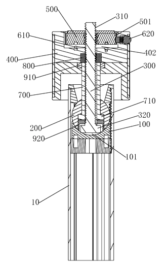
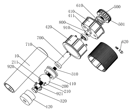
Drawings reproduced from the public patent document for reference.