
Patent CN220937112U
Updated November 8, 2026Hair Dryer Nozzle with Airflow-Driven Swing Member
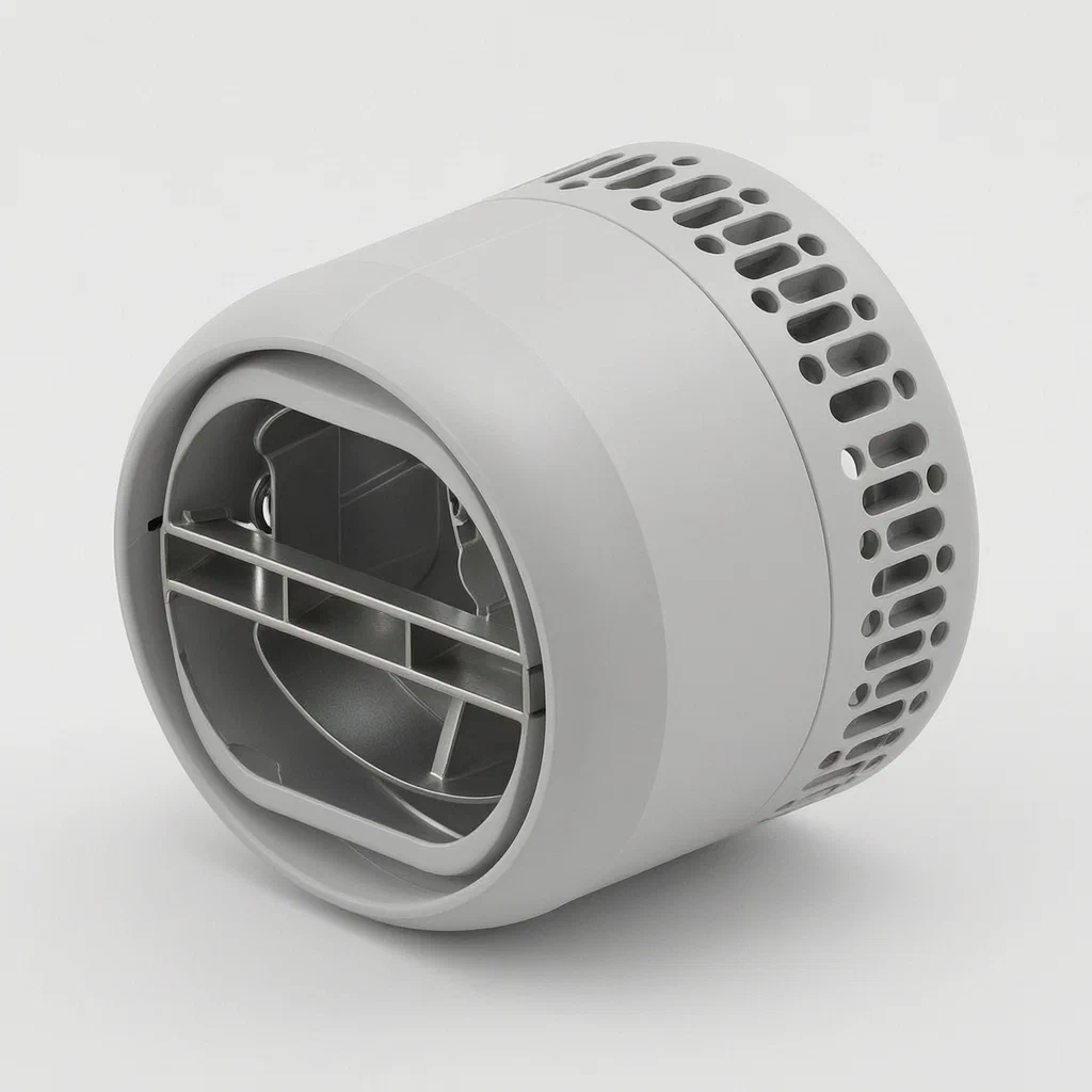
Standard hair dryer nozzles produce a static cone of air, forcing users to constantly move their wrists to distribute heat evenly across long sections of hair. This often leads to arm fatigue and uneven drying. This patent describes a nozzle with a passive swing mechanism. By allowing external air to enter through side inlets, the airflow velocity and pressure increase within the duct. This energized stream strikes a rotatable swing member, causing it to oscillate back and forth naturally. The result is an automatic deflection of the airflow, spreading heat over a wider area without requiring active user motion or complex mechanical parts.
- China utility model - in force
- No filings outside China
- Personal care appliances
- Passive airflow-driven oscillation
Splat! What let you down?
🌬️
Passive Oscillation
The swing member moves solely due to airflow pressure; no motor or battery required.
🔄
Air Intake Design
Side holes draw in external air to boost flow speed and stabilize the stream before hitting the swing piece.
📐
Dual Housing Structure
An inner converging section and outer stabilizing shell work together to direct air precisely onto the pivot.
🔧
Simple Assembly
Rotatable shaft connection allows easy manufacturing and maintenance compared to geared mechanisms.
Bring this product to market
- ✓ Patent review Patent family and legal status reviewed in the relevant jurisdictions.
- 2 Product brief · now How it works, uses and options written up
- 3 Prototype First samples for buyers to review
- 4 Pilot run Small first batch for launch customers
- 5 Volume production Repeat orders at scale
Buyer interest
– of 100 buyers needed to start prototyping
One click, no sign-up. Each vote is one real visitor, and products with the most interest go to prototyping first.
Build team: no members yet. Need a partner, co-funding or skills to build this? Join and we introduce the team once it forms.
Patent Rights & Team Participation
Before joining a development team, participants should ensure they have the necessary rights or authorization to participate in the project.
Participation is generally appropriate where:
- You own the relevant patent rights or have obtained permission or a license from the rights holder.
- The relevant patent rights have expired or have been legally invalidated in the jurisdictions where the planned activities will take place.
- The planned development, manufacturing, and commercialization activities have been independently assessed and do not infringe applicable patent rights in the relevant jurisdictions.
Important: Being located outside a country where a patent is protected does not automatically exempt you from patent infringement risks. Patent rights may apply based on where development, manufacturing, use, sale, or import activities take place.
IP2M does not grant any patent license or authorization through team participation. Joining a project does not provide permission to use, manufacture, or commercialize patented technology.
The problem
Traditional hair dryer attachments typically function as static concentrators or diffusers. When using a concentrator, the user must manually rotate their wrist or move the dryer head continuously to ensure even heat distribution across a section of hair. This repetitive motion causes arm fatigue during long styling sessions, especially for users with thick or long hair. Conversely, diffusers spread air too broadly and lose directional control. There is a need for an attachment that actively deflects the airflow to cover a wider area dynamically, reducing the physical effort required by the user while maintaining the directed nature of a nozzle. Existing solutions often rely on electronic oscillators, which add weight, cost, and potential failure points due to motors and wiring.
The solution
The patent introduces a nozzle assembly where the airflow itself powers the movement.
- A housing forms an air duct connected to the blower’s outlet.
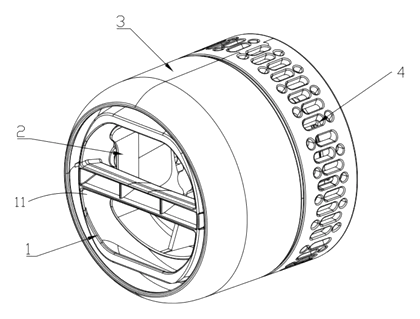
- Multiple air inlet holes penetrate the housing walls, allowing ambient air to enter the duct.
- This incoming air converges with the primary airflow from the dryer, increasing its velocity and pressure due to the Venturi-like effect described in the text.
- A swing member is rotatably fixed within this high-pressure path.
- As the accelerated air strikes the swing member, it causes the member to oscillate reciprocally.
- This oscillation deflects the exit airflow path, creating a sweeping motion automatically.
Who it is for
- Personal Care Brands: Companies looking to differentiate their hair dryer accessories with ergonomic, motor-free oscillation features.
- Appliance Manufacturers: OEMs seeking to reduce component count and assembly complexity compared to electronically driven swinging heads.
- Salon Equipment Suppliers: Professionals who value lightweight tools that reduce stylist arm strain during blowouts.
- Consumer Electronics Integrators: Firms attaching smart handles to dryers, where a passive nozzle avoids competing for power or space.
How it works
The main parts
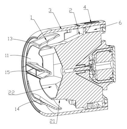
| No. | Part | What it does |
|---|---|---|
| 1 | Swing Member | Rotates on a shaft; deflects airflow when struck by air. |
| 2 | First Housing | Inner tube forming the main air duct; has a converging end. |
| 3 | Second Housing | Outer shell; stabilizes airflow and provides structural support. |
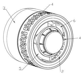
| 4 | Air Inlet Holes | Openings in side walls allowing external air to enter the duct. |
| 5 | Air Inlet | Connection point to the hair dryer body. |
| 6 | Air Flow Channel | Space between housings guiding mixed air toward the swing member. |
Operating Steps
- Air Entry: Hot air enters from the dryer into the First Housing (2).
- Mixing: External air is sucked in through Air Inlet Holes (4), merging with the main stream.
- Acceleration: The combined flow passes through the converging section of the First Housing, increasing speed.
- Impact: The high-speed jet hits the Swing Member (1).
- Oscillation: The force pushes the member away; its return mechanism (gravity/air balance) brings it back, causing continuous reciprocation.
- Deflection: The moving member redirects the exiting air beam in a sweeping arc.
Applications
Daily Home Styling
Users with long hair can hold the dryer steady while the nozzle sweeps the air across strands, reducing wrist rotation needed for even drying.
Salon Blowouts
Stylists working on multiple clients experience less arm fatigue because the nozzle automates the lateral movement usually done by hand.
Travel Accessories
Since the mechanism is passive and contains no batteries or motors, the nozzle remains lightweight and compact for carry-on luggage.
Kids’ Hair Drying
Parents can use a stationary hold position, letting the gentle sweep prevent overheating any single spot on delicate children’s hair.
Where it is less suitable
- Precision Spot Treatment: The oscillating nature spreads heat, making it unsuitable for targeting very small sections like baby hairs.
- High-Velocity Pro Tools: Some professional dryers have extremely high CFM that might overpower the passive swing range, requiring tuned weights.
- Cold Air Settings: Without sufficient thermal expansion or specific tuning, low-velocity cold shots may not generate enough force to initiate oscillation reliably.
Patent & Production
At a glance
| Patent number | CN220937112U (application CN202322624144) |
| Type | China utility model (实用新型) - protects product shape and structure |
| Original title | Nozzle for hair dryer and hair dryer having same (一种吹风机用风嘴及具有其的吹风机) |
| Patent owner | Suzhou Simple Youwei Technology Co Ltd |
| Inventors | Qian Zhong, Zhu Chao, Zhang Mingshun |
| Filing date | 2023-09-26 |
| Grant date | 2024-05-14 |
| Status (China) | In force - valid until at most 2033-09-26 (assuming annual fees are paid) |
| Patent family | Public record shows Chinese filings only - no US, European, Japanese, PCT or other filings listed |
| Cited by | 2 later documents |
| Source | Google Patents (search for CN220937112U) |
What the claims cover, in plain language
Claim 1 defines a nozzle comprising a housing with an air duct. Key features include a swing member rotatably fixed on the housing, positioned in the airflow path to deflect it. Crucially, the housing has multiple air inlet holes penetrating its walls. These holes allow external air to enter the duct, converge with the blower’s air, and form the airflow path that drives the swing member. The swing member is located downstream of these inlets.
Claim 2 specifies that the oscillation is passive, driven solely by the air flow. Claims 3-5 describe a two-part housing structure: a first housing (inner duct) and a second housing (outer shell). The first housing may have a converging section to accelerate air. The second housing encloses the swing member and first housing, providing stability. Claims 6-8 detail the placement of air inlet holes on the side walls of either or both housings, and the formation of an air flow channel between the housings to guide external air inward. Claim 9 describes the swing member’s construction: a cover body with a rotating shaft and two swing arms positioned on either side of the airflow path. Claim 10 covers the complete hair dryer assembly including this nozzle.
This is a simplified reading for orientation only. The legal scope is defined by the exact claim wording in the official Chinese document.
What this means for US production
This patent was filed in China and is currently in force. Making or selling this specific configuration in China requires the owner’s permission. However, the public record shows no US counterpart. Therefore, this Chinese patent does not restrict manufacturing or sales in the United States based on this document alone.
Two practical questions should be settled early:
- Other patents may exist. Hair dryer attachments are a crowded field. While this specific passive-swing mechanism appears unique in this filing, prior art on oscillating nozzles, venturi-effect attachments or dual-housing structures may belong to major appliance manufacturers. We recommend a freedom-to-operate (FTO) review before tooling.
- Mechanical Tolerances. The effectiveness of the passive swing depends heavily on the precision of the rotating shaft and the angle of the swing arms. Variations here can stop the oscillation or cause jamming.
Customization and manufacturing
What can be customized
| Area | Options |
|---|---|
| Material | High-temp ABS, PC, or Nylon for durability against heat. |
| Finish | Matte soft-touch, glossy, or electroplated accents. |
| Swing Angle | Adjusted by changing the length/weight of swing arms or pivot friction. |
| Inlet Pattern | Number and size of air holes to tune airflow convergence. |
| Color | Custom Pantone matching for brand alignment. |
| Attachment | Clip-on, screw-on, or bayonet mount compatibility. |
Things to plan for (US market)
- UL 859 / IEC 60335: Safety standards for household electric appliances. Even though the nozzle is plastic, it attaches to a mains-powered device, so material flammability ratings (e.g., UL94 V-0) are critical.
- FDA Compliance: If marketed for medical use or if materials contact skin closely, biocompatibility checks may apply, though standard cosmetic use usually relies on general safety standards.
- Proposition 65: Ensure plastics and plating materials do not contain restricted chemicals above safe harbor levels.
How a project runs
- Inquiry - Define compatible dryer models, desired swing amplitude, and aesthetic preferences.
- Design - CAD modeling of the dual-housing system and airflow simulation to verify passive oscillation.
- Prototype - 3D-printed housings and CNC-machined swing members for fit and function testing.
- Pilot Run - Injection molded samples tested for swing consistency, noise, and heat resistance.
- Production - Mass molding, assembly of swing mechanisms, quality control checks.
Quantities & timeline
Tooling for the dual-housing structure and the swing member requires precision molds to maintain tight tolerances for the rotating shaft. Airflow tuning takes time to ensure the passive mechanism triggers reliably at typical dryer speeds. Send us your target dryer compatibility list, material specs, quantity, and desired swing characteristics and we will reply with options.
Production notes
Tooling and process
Injection molding is likely used for the first and second housings to achieve the complex internal channels. The swing member may also be molded, with a separate metal or hardened plastic pin for the pivot. Electroplating could be applied for decorative finishes on the outer shell.
Cost drivers
Mold complexity for the dual-housing interlock is likely a significant factor. Material grade affects heat resistance costs. Plating thickness and seal quality around the pivot point influence cost. Packaging designed to protect the fragile swing mechanism adds cost.
Prototyping path
Start with 3D-printed housings to validate fit. Off-the-shelf bearings or bushings are typically used for initial swing tests. Water spray or airflow tests would likely follow, to check for leakage or instability. Proceed to tooling once the passive oscillation frequency is stable.
What we would change before tooling
We would likely adjust the pivot friction to prevent freezing in heat. The air inlet hole size would typically be optimized to give sufficient pressure buildup for reliable swinging. We would also verify the snap-fit strength between the two housings to withstand vibration.
Common failure points
Water ingress at seams if used in humid environments. Plating flaking due to heat cycling. Hinge fatigue if the swing arm material is too brittle. Mold/mildew in trapped water if the design doesn’t drain properly. Suction cup hardening is not applicable here, but rubber seals may degrade.
Patent drawings
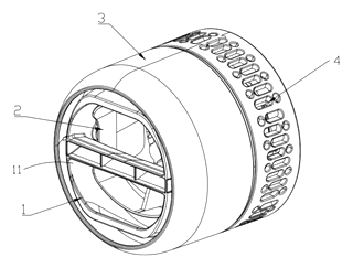
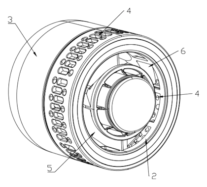
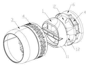
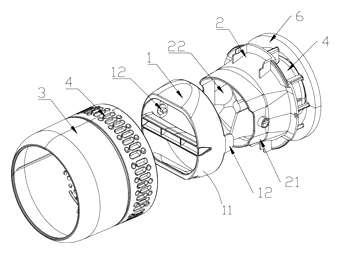
Drawings reproduced from the public patent document for reference.
Frequently asked questions
Does this nozzle require batteries or a motor?
No. The patent describes a passive mechanism. The airflow from the hair dryer itself drives the swing member. The design uses air inlet holes to increase pressure and velocity, which physically pushes the rotating part back and forth.
Will it work with any hair dryer?
It depends on the attachment interface. The patent covers the nozzle structure, but compatibility with specific dryer brands (like Dyson, Shark, or generic round barrels) requires custom mounting adapters. We can design mounts for common barrel diameters.
Why are there holes on the side of the nozzle?
These are air inlet holes. They allow outside air to enter the duct and mix with the hot air from the dryer. This mixing increases the overall airflow volume and speed, providing the force needed to make the internal swing member oscillate.
Is the swinging motion adjustable?
Yes, during the design phase. The amplitude and speed of the swing can be tuned by adjusting the weight of the swing arms, the friction of the pivot, and the size of the air inlets. Set in design / confirmed on prototypes.
Can this design be made and sold in the US?
The patent was filed in China and is in force there. The public record shows no US counterpart, so this specific Chinese patent does not restrict the design in the US. However, hair dryer accessories are subject to many other patents. We recommend a freedom-to-operate check before volume production to ensure no other US patents are infringed.
Are you affiliated with the patent owner?
No. IP2M is an independent design and manufacturing service working from the public patent document.
Request a quote
Click Request a Quote below to see our email address - copy it, or open your email app with a ready-made message. Please mention patent CN220937112U in the subject.
Helpful details to include:
- Your company and channel (personal care brand, appliance maker, accessory retailer)
- Target dryer models or barrel diameter specifications
- Desired swing angle and frequency (if known)
- Material preferences (heat rating, color, finish)
- Estimated quantity and target price
- Timeline - when you would like samples and the first shipment
You can also reach us at (332) 203-9997.
Page editor: Daniel Chen, Product Research Editor · IP2M
Last updated November 8, 2026. If something on this page looks wrong, email [email protected] and we will check it against the patent.
Interested in building this?
Tell us your target market, quantity and timeline. We reply with options for prototyping, small-batch runs or volume production.
Send your inquiry to
Please put CN220937112U in the subject line and tell us your company, country, estimated quantity and timeline.
Prefer to talk? Call (332) 203-9997.
More product-ready patents
All Bath & Personal Care patents →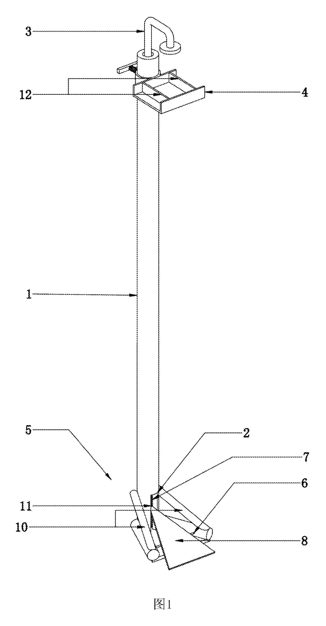
Bath & Personal Care
Foot-Pedal Soap & Sanitizer Dispenser Stand
Hands-free, battery-free dispenser stand - step on a pedal to press the pump of any soap or sanitizer bottle.
Patent CN207461995U
Bath & Personal Care
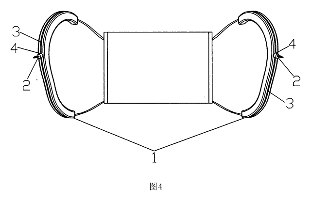
Ear-Shaped Mask Strap Guard with Tension Adjuster
Ear-shaped silicone guard and strap-length adjuster that make ear-loop masks comfortable to wear for long hours.
Patent CN205456233U
Bath & Personal Care
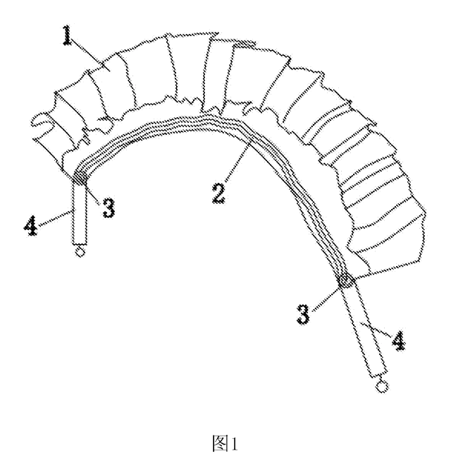
Adjustable-Length Back Scrubber Strap with Push-Button Handles
Back-scrubber strap with push-button handles that set its length and a spring that keeps it taut.
Patent CN207041452U
Bath & Personal Care
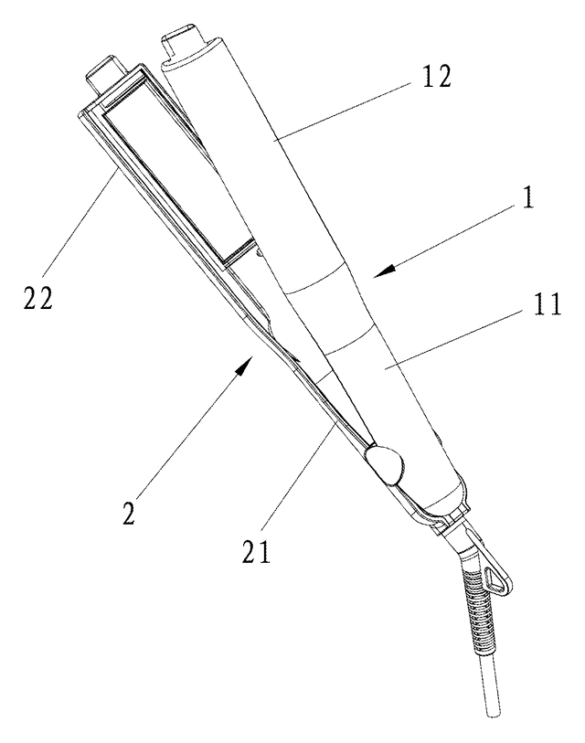
Angled-Plate Hair Straightener
Flat iron with plates twisted 45-75° to the handle, a curling groove and rubber-capped tips.
Patent CN206137462U
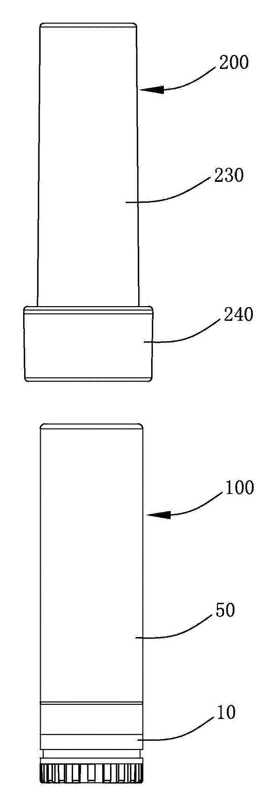
Bath & Personal Care
Refillable Lipstick Case with Sealed Snap-In Refill Pods
Reusable twist-up lipstick case; sealed refill pods unlock at the top of the stroke for shade swaps.
Patent CN206909979U
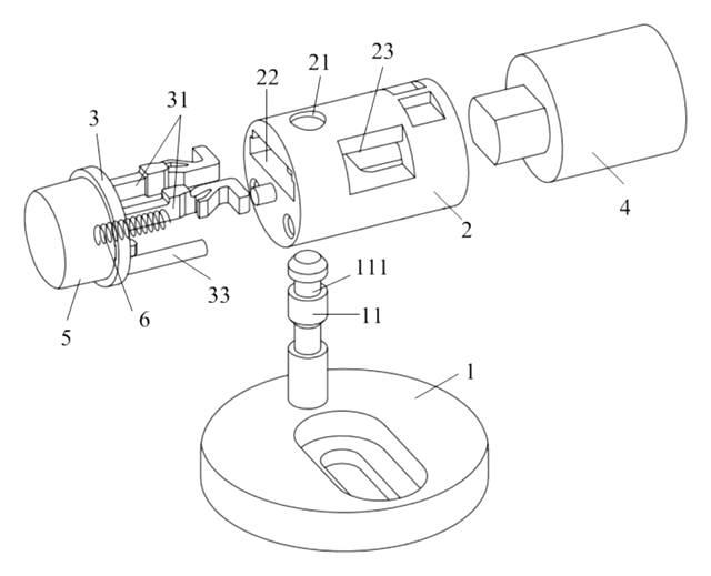
Bath & Personal Care
Quick-Release Toilet Seat Hinge with a Push-Button Two-Strip Latch
Toilet seat hinge: drop the shaft onto a grooved post to lock; one push parks the latch open to lift it off.
Patent CN210370292U
Browse by category
- Apparel & Accessories (50)
- Baby & Kids (29)
- Bags & Luggage (17)
- Bath & Personal Care (33)
- Car Accessories (26)
- Furniture, Bedding & Storage (25)
- Garden & Outdoor (34)
- Health & Wellness (14)
- Home, Kitchen & Cleaning (52)
- Lighting (24)
- Packaging & Containers (13)
- Pet Products (12)
- Phone & Camera Accessories (9)
- Retail Display (26)
- School, Office & Art (38)
- Sports & Recreation (48)
- Tools & Workshop (56)
- Toys & Games (23)
This page is based on the public patent document CN220937112U, assigned to Suzhou Simple Youwei Technology Co Ltd. IP2M is an independent manufacturing service and is not affiliated with, endorsed by or licensed by the patent owner. Images marked as concept renderings are illustrations, not photos of an existing product. Patent status information is provided for reference only and is not legal advice; confirm freedom to operate for your market before production. Full disclaimer.