At a glance
| Patent number | CN222445290U (application CN202420697856) |
| Type | China utility model (实用新型) - protects product shape and structure |
| Original title | Fan vehicle capable of adjusting wind resistance (一种可调节风阻的风扇车) |
| Patent owner | Xiamen K Power Sports Co ltd |
| Inventors | Wei Zhaogui, Wen Tianrong, Zhong Wenfu |
| Filing date | 2024-04-07 |
| Grant date | 2025-02-11 |
| Status (China) | In force - valid until at most 2034-04-07 if annual fees are paid |
| Patent family | Chinese filings only - no US, European, Japanese, PCT or other filings listed |
| Cited by | 1 later document |
| Source | Google Patents (search for CN222445290U) |
What the claims cover, in plain language
Claim 1 defines a fan vehicle with a frame, pedals, and a wind wheel. The key feature is that the wind wheel has blades that can autorotate around their own shafts. An operating mechanism is linked to these blades to drive this rotation, thereby changing the windward area and adjusting the windage (resistance).
Claim 2 specifies that the blade rotating shafts lie in a plane perpendicular to the wind wheel’s main axis. Claim 3 details the wind wheel structure: a linkage member connected to the pedals, and a blade connecting assembly that allows the blades to rotate. Claim 4 describes the blade connecting assembly using a sleeve and a rotating member within a hole. Claim 5 outlines the operating mechanism: a slider moves relative to the rotor shaft, connected to each blade via a linkage assembly, so sliding the mechanism rotates all blades simultaneously. Claim 6 specifies the linkage assembly uses three hinged rods (first, second, third) to convert the slider’s linear motion into blade rotation. Claims 7-9 define the blade geometry: cross-section shape (middle large, ends small), elongate profile, maximum 90-degree rotation, and aspect ratio 2-3. Claim 10 mentions handles with staggered gripping portions.
This is a simplified reading for orientation only. The legal scope is defined by the exact claim wording in the official Chinese document.
What this means for US production
This patent was filed only in China and is currently in force there. It has no US or other foreign counterpart. Therefore, making or selling this specific design in the United States does not infringe this Chinese patent. However, since the technology involves novel mechanical structures for fitness and recreation, other patents may exist in the US field.
Two points to settle early:
- Other patents may exist. Variable resistance mechanisms for exercise equipment are a heavily patented area. While this specific Chinese patent does not block US sales, a freedom-to-operate (FTO) review is recommended to ensure the blade-linkage system does not conflict with existing US patents held by major fitness brands.
- Structural Integrity. The blades experience significant centrifugal and aerodynamic forces. Material selection and joint design must withstand these loads without failure, especially if used outdoors.
Customization and manufacturing
What can be customized
| Area | Options |
|---|---|
| Frame Material | Aluminum extrusion for lightness; steel stamping for cost efficiency. |
| Blade Material | Glass-filled nylon injection molding for strength and weather resistance. |
| Wheel Diameter | Scaled to fit different vehicle sizes (e.g., compact trainer vs. large cart). |
| Handle Type | Standard lever, rotary dial, or integrated grip with self-locking mechanism. |
| Finish | Powder coating, anodizing, or raw metal finish depending on indoor/outdoor use. |
| Resistance Range | Adjusted by blade surface area and maximum rotation angle (up to 90°). |
Things to plan for (US market)
- ASTM F1487 - Standard Consumer Safety Performance Specification for Playground Equipment for Public Use (if adapted for public parks).
- CPSC Guidelines - General safety requirements for children’s products if marketed to minors (though primarily adult/recreational).
- UL Standards - If the design is integrated with electronic sensors or motors (not part of this pure mechanical patent, but common in modern hybrids), UL certification may apply.
- California Prop 65 - Screening for lead, cadmium, and other chemicals in plastics and coatings.
How a project runs
- Inquiry - Define target user (indoor/outdoor), load capacity, and aesthetic preferences.
- Design - Finalize blade geometry, linkage ratios, and frame dimensions.
- Prototype - Create functional samples to test resistance linearity and mechanical durability.
- Pilot Run - Small batch production to validate assembly processes and material tolerances.
- Production - Injection molding for blades, extrusion/cutting for frames, assembly.
Quantities & timeline
Tooling costs are driven by the number of molds required for the plastic blades and linkage components. Metal fabrication time depends on whether standard extrusions or custom stamped parts are used. Certification testing for structural integrity adds to the pre-production timeline. Send us your target quantity, material preference, and intended application (indoor/outdoor) and we will reply with options.
Production notes
Tooling and process
Glass-filled nylon injection molding is likely the primary process for the blades and linkage sleeves due to the need for impact resistance and dimensional stability. Aluminum extrusion would typically form the main frame structure. Stamping might be used for smaller bracketry or fastener plates. Snap-fit assemblies could reduce screw counts for internal linkage joints.
Cost drivers
The number of molds is a significant cost factor, particularly for the complex blade connecting assemblies. Impact grade material choices influence resin costs. Fastener count affects assembly labor time. Weight considerations may drive material thickness, impacting both raw material usage and shipping logistics. Packaging design must accommodate the potentially large diameter of the wind wheel.
Prototyping path
Initial prototypes would likely use 3D-printed parts for the linkage mechanisms to verify kinematics. Machined aluminum frames allow for quick adjustments to blade spacing. Functional samples should undergo impact testing to simulate crash scenarios or drop tests during assembly. Tooling decisions follow validation of these functional samples.
What we would change before tooling
Wall thickness and joint design of the blade roots likely need careful review to prevent stress concentration. Hinge boss and pivot wear points should be reinforced or bushed to extend service life. Edge hardness and wear resistance of the contact surfaces between sliders and rods require specification to avoid premature binding.
Common failure points
Cracking under impact is a risk for brittle plastics if not properly glass-filled. Bolts loosening due to vibration from the spinning wheel is a common issue; thread-locking agents or prevailing torque nuts are advisable. UV degradation of nylon blades may occur if used outdoors without stabilizers. Weight above target specifications could result from over-engineering the frame for safety margins.
Patent drawings
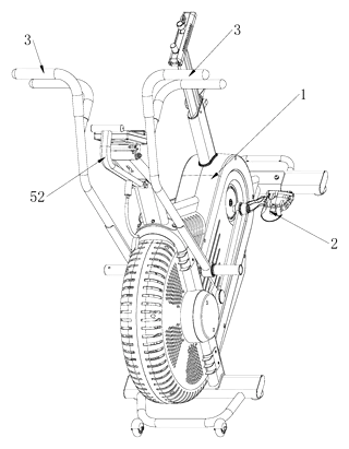
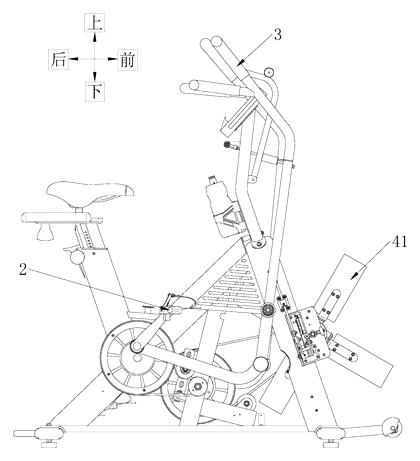
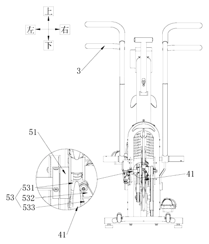
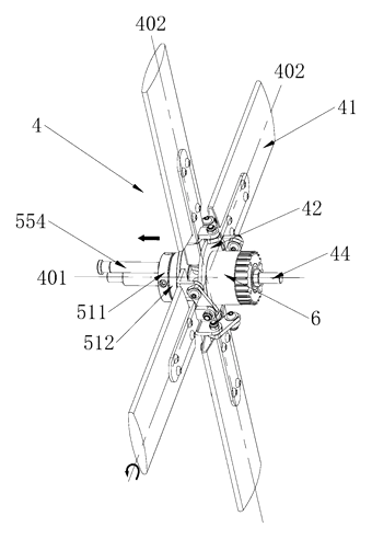
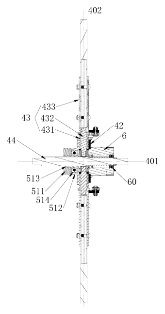
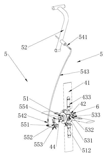
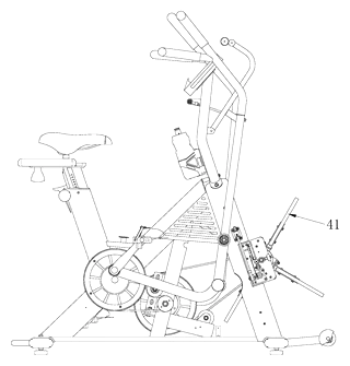
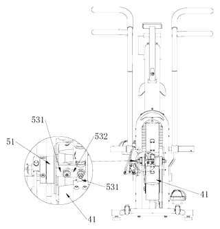
Drawings reproduced from the public patent document for reference.