
Patent CN108685518B
Updated November 8, 2026Automated Toilet Seat Cover Dispenser with Vacuum Suction
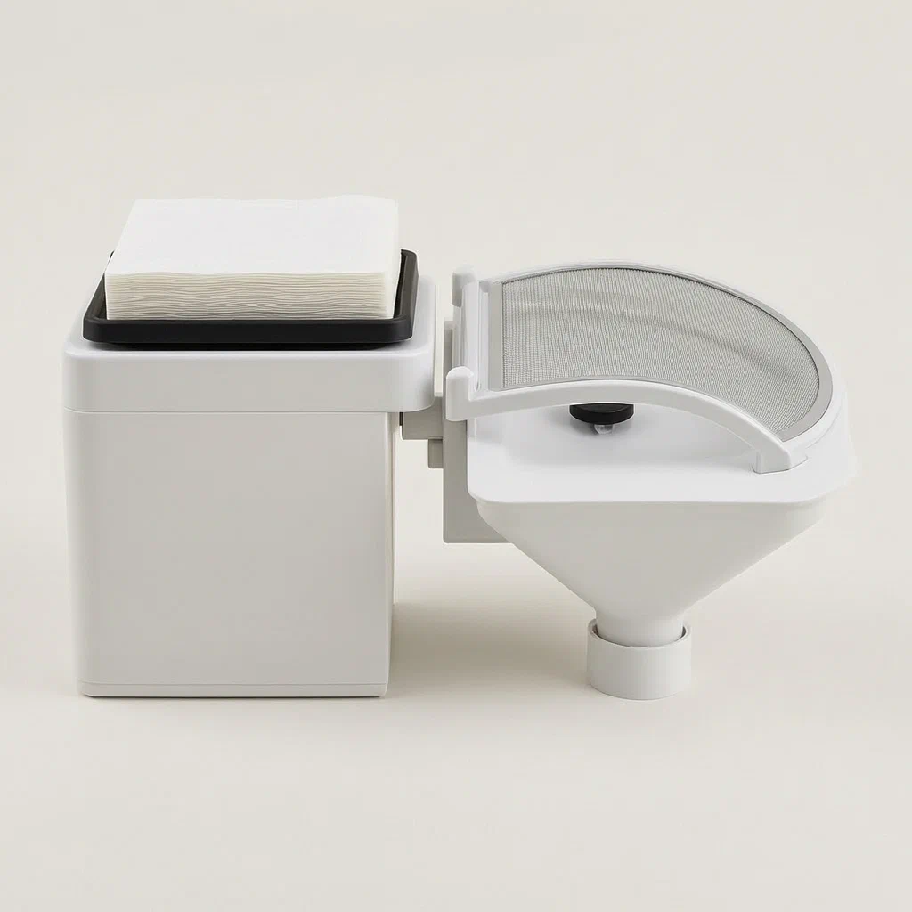
Manual application of toilet seat covers is slow and often results in misalignment or dropped sheets. This automated system integrates the dispenser directly into the toilet lid structure. It uses a vertical stack of water-soluble paper held by an adjustable backing plate. Infrared sensors monitor the paper level. When a new cover is needed, air jets blow between the top two sheets to separate them. Vacuum suction cups on the lid's underside lift the single top sheet. The lid then rotates, carrying the paper to the seat surface. A secondary vacuum system holds the paper flat against the seat until the user sits. This design eliminates the need for manual handling and ensures consistent placement.
- China invention patent - active
- No filings outside China
- Sanitary ware accessories
- Vacuum suction, air separation, IR sensing
Splat! What let you down?
📄
Air Separation
Blowers inject air between stacked sheets to prevent double-pickup errors.
🔄
Rotary Application
The lid rotates 180 degrees to place the cover precisely on the seat.
📏
Auto Height Adjust
Cylinder-driven backing plate raises as paper is consumed to maintain feed level.
🔒
Vacuum Hold
Suction cups secure the paper during transport and release it onto the seat.
Bring this product to market
- ✓ Patent review Patent family and legal status reviewed in the relevant jurisdictions.
- 2 Product brief · now How it works, uses and options written up
- 3 Prototype First samples for buyers to review
- 4 Pilot run Small first batch for launch customers
- 5 Volume production Repeat orders at scale
Buyer interest
– of 100 buyers needed to start prototyping
One click, no sign-up. Each vote is one real visitor, and products with the most interest go to prototyping first.
Build team: no members yet. Need a partner, co-funding or skills to build this? Join and we introduce the team once it forms.
Patent Rights & Team Participation
Before joining a development team, participants should ensure they have the necessary rights or authorization to participate in the project.
Participation is generally appropriate where:
- You own the relevant patent rights or have obtained permission or a license from the rights holder.
- The relevant patent rights have expired or have been legally invalidated in the jurisdictions where the planned activities will take place.
- The planned development, manufacturing, and commercialization activities have been independently assessed and do not infringe applicable patent rights in the relevant jurisdictions.
Important: Being located outside a country where a patent is protected does not automatically exempt you from patent infringement risks. Patent rights may apply based on where development, manufacturing, use, sale, or import activities take place.
IP2M does not grant any patent license or authorization through team participation. Joining a project does not provide permission to use, manufacture, or commercialize patented technology.
The problem
Standard toilet seat cover dispensers require users to manually pull a sheet from a wall-mounted box and align it on the seat. This process is cumbersome, often leads to wrinkled or misplaced covers, and increases contact with shared surfaces. Existing automatic mechanisms sometimes struggle with separating individual sheets from a stack, causing jamming or multiple sheets being dispensed at once. Furthermore, integrating a reliable feeding mechanism into the existing geometry of a toilet lid without modifying the seat shape remains a challenge for manufacturers.
The solution
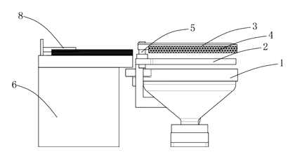
- A toilet lid (3) is articulated to the base via a pivot (5).
- Behind the lid, a paper feed mechanism includes a box (6) holding a reference column (61) for the paper stack.
- An air blowing device (63) separates the top sheet from the stack using air pressure.
- Infrared altitude sensors (62) monitor the paper level to trigger adjustments.
- Vacuum suction cups (32) on the underside of the lid pick up the separated sheet.
- An arc-shaped baffle (4) slides along the lid’s outer wall to guide movement and protect the paper stack.
- A height adjustment mechanism (cylinder shaft) raises the backing plate as sheets are used.
Who it is for
- Smart toilet manufacturers looking to integrate automated hygiene features into premium models.
- Public restroom equipment suppliers needing touch-free solutions for high-traffic facilities.
- Hotel and hospitality brands seeking to upgrade bathroom amenities with automated convenience.
- OEM designers developing next-generation sanitary ware with integrated mechanical systems.
How it works
The main parts
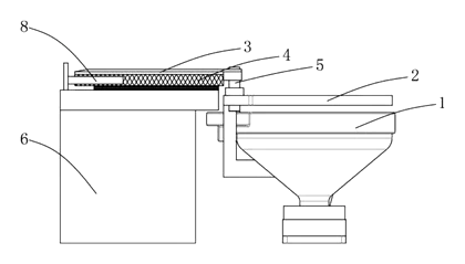
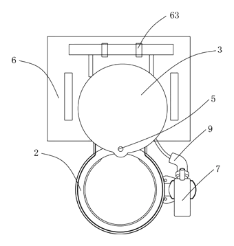
| No. | Part | What it does |
|---|---|---|
| 1 | Toilet Base | Standard mounting structure. |
| 2 | Seat Ring | The surface receiving the paper cover. |
| 3 | Lid | Rotates to apply the cover; carries suction cups. |
| 4 | Arc Baffle | Slides on the lid to clear the paper stack path. |
| 5 | Pivot | Hinge connecting lid to base. |
| 6 | Feed Box | Houses the paper stack and control elements. |
| 61 | Reference Column | Central post holding the paper roll/stack. |
| 62 | IR Sensor | Detects paper height for automation logic. |
| 63 | Air Blower | Separates sheets before pickup. |
| 32 | Suction Cups | Vacuum elements on the lid underside. |
| 7 | Air Pump | Provides vacuum and air pressure. |
Operating Steps
- Preparation: The lid opens, revealing the paper stack in the rear box. The baffle slides up to clear the path.
- Separation: Air jets from device (63) blow between the top two sheets, breaking static cling.
- Pickup: Vacuum suction cups (32) engage the top sheet, lifting it off the stack.
- Transport: The lid rotates 180 degrees downward toward the seat, carrying the paper.
- Application: The lid descends slightly. Vacuum holes in the baffle (41) or seat area help hold the paper flat.
- Release: Suction releases, leaving the cover on the seat. The lid returns to its resting position.
- Reset: The backing plate rises one step via the cylinder mechanism to prepare the next sheet.
Applications
Smart Home Bathrooms
Homeowners upgrading to smart toilets benefit from the hands-free application, reducing contact with potentially contaminated surfaces and ensuring the cover is perfectly aligned every time.
High-Traffic Public Restrooms
In airports or malls, this mechanism speeds up turnover between users. The automated nature reduces the frequency of manual refills required by staff compared to traditional dispenser boxes that jam easily.
Hotel Guest Rooms
Hotels can offer a premium hygiene experience. The silent operation of the air-blow separation and vacuum pickup maintains the quiet atmosphere expected in luxury accommodations while providing visible cleanliness assurance.
Healthcare Facilities
Touch-free environments are critical in clinics and hospitals. This device minimizes the need for patients or staff to handle the dispenser mechanism directly, lowering the risk of cross-contamination.
Where it is less suitable
- Low-cost basic toilets - The complexity of pumps, sensors, and actuators makes this unsuitable for budget fixtures.
- Non-standard seat shapes - The specific alignment of the suction cups and rotation axis requires a standard oval or round seat geometry.
- Areas with extreme humidity - While designed for bathrooms, excessive steam may affect sensor reliability if not properly sealed.
Patent & Production
At a glance
| Patent number | CN108685518B (application CN201810533619) |
| Type | China invention patent (发明专利) - protects product shape, structure, and method |
| Original title | Intelligent closestool lid trades packing paper device (智能马桶盖换垫纸装置) |
| Patent owner | Ningbo Jingjie International Logistics Co ltd |
| Inventors | Ge Lianhua |
| Filing date | 2018-05-29 |
| Grant date | 2020-07-07 |
| Status (China) | In force - valid until at most 2038-05-29, subject to payment of annual fees |
| Patent family | Public record shows Chinese filings only - no US, European, Japanese, PCT or other filings listed |
| Cited by | 0 later documents |
| Source | Google Patents (search for CN108685518B) |
What the claims cover, in plain language
Claim 1 - An intelligent toilet lid paper changing device comprising a toilet body, a seat ring, and a lid. The lid is hinged via a pivot. A paper feed mechanism is located behind the lid, containing a box with a reference column for the paper. Key features include an air blowing device for separating paper, infrared altitude sensors on the sides of the column, and a rotatable elastic pressure plate. The lid’s lower end has multiple suction cups. An arc-shaped baffle on the lid’s outer side slides in a groove to move relative to the lid, preventing interference with the paper stack during rotation. Clamping plates press the baffle.
Claim 2 - Adds an air pump connected to the suction cups via pipes to provide vacuum.
Claim 3 - Specifies the height adjustment mechanism uses a cylinder shaft and cylinder to raise the backing plate.
Claim 4 - Details that the air blowing device has multiple blowing holes.
This is a simplified reading for orientation only. The legal scope is defined by the exact claim wording in the official Chinese document.
What this means for US production
This patent was filed in China and is currently in force. Making or selling this specific configuration in China would require the owner’s permission. However, the public record shows no US counterpart. Therefore, the Chinese patent itself does not restrict manufacturing or sales in the United States.
Two points to settle early:
- Other patents may exist. Automated toilet seat cover dispensers are a competitive field. US companies like Tushy or various sanitary ware giants may hold patents on similar vacuum-based or rotating application methods. A freedom-to-operate (FTO) review is essential to check for US patents covering “vacuum applied seat covers” or “rotating lid dispensers” before tooling.
- Integration complexity. This design relies on precise alignment of baffles, sensors, and vacuum channels. Modifying the lid shape or seat geometry to fit different toilet models may alter the functional relationship described in the claims, potentially avoiding infringement but requiring significant re-engineering.
Customization and manufacturing
What can be customized
| Area | Options |
|---|---|
| Paper Type | Water-soluble tissue, standard disposable covers (adjust hole spacing) |
| Actuation | Pneumatic cylinders vs. electric linear actuators for height adjust |
| Sensors | IR distance sensors, capacitive proximity switches |
| Vacuum Source | Integrated mini-pump vs. external mains-powered pump |
| Material | ABS/PC housing, stainless steel brackets, silicone seals |
| Control Logic | PLC integration, Bluetooth/Wi-Fi connectivity for app control |
Things to plan for (US market)
- UL 60335-1 / UL 60335-2-10 - Safety standards for household electrical appliances, specifically those involving water and electricity (toilets/bidets).
- FCC Part 15 - If wireless controls (Bluetooth/Wi-Fi) are added for door lock integration or app control.
- IPC WaterSense - While not mandatory for accessories, compatibility with low-flow toilets may require careful hydraulic design if water lines are involved.
- NSF/ANSI 372 - Lead content limits for materials contacting potable water (if any water lines are part of the assembly).
How a project runs
- Inquiry - Define toilet model compatibility, paper size, and power requirements.
- Design - CAD modeling of lid interface, baffle sliding tracks, and vacuum channel routing.
- Prototype - 3D printed housings, off-the-shelf vacuum pumps, and sensor testing.
- Pilot Run - Cycle life testing, humidity exposure tests, and noise verification.
- Production - Injection molding for plastic parts, CNC machining for metal brackets, PCB assembly.
Quantities & timeline
Tooling costs are driven by the precision required for the sliding baffle mechanism and the multi-cavity molds for the suction cup arrays. Certification for electrical safety (UL) adds significant lead time. Send us your target toilet models, paper specifications, and volume estimates and we will reply with options.
Production notes
Tooling and process
Injection molding is likely the primary process for the lid and box housings, given the complex internal channels for air and vacuum. Stainless steel forming may be used for the reference column and structural supports. Electroplating could be applied to decorative metal accents. Silicone molding is typically used for the suction cups to ensure a good seal against the paper.
Cost drivers
Plating grade and thickness likely affect the aesthetic finish and corrosion resistance in humid environments. Seal and gasket quality is critical to maintaining vacuum pressure; poor seals increase failure rates. Material grade for the plastic must withstand repeated flexing and moisture. Packaging must protect delicate sensor alignments during shipping.
Prototyping path
We would typically start with a 3D-printed housing to verify the sliding baffle geometry. Use off-the-shelf seals and vacuum cups for initial function tests. A water spray test sample is necessary to validate IP ratings. Conduct plating trials on coupons to match the final look. Finalize tooling after confirming the actuator forces.
What we would change before tooling
We would likely replace the manual clamping plates with a snap-fit or screw-retained assembly for easier maintenance. The wire routing and strain relief for the sensors should be redesigned to prevent pinching during the lid’s rotation cycle. We would also simplify the air blowing nozzle array to reduce clogging risks.
Common failure points
Water ingress at seams is a major risk due to the bathroom environment. Plating flaking or corrosion can occur if the coating is too thin. Suction cup hardening over time may reduce grip strength. Mold and mildew can develop in trapped water within the air channels. Hinge fatigue is possible if the motor torque is miscalculated.
Patent drawings
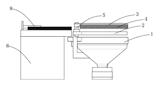
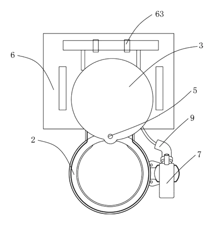
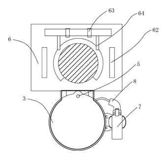
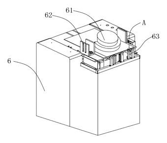
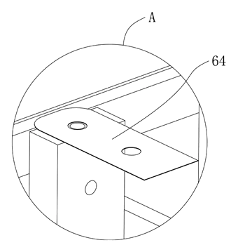
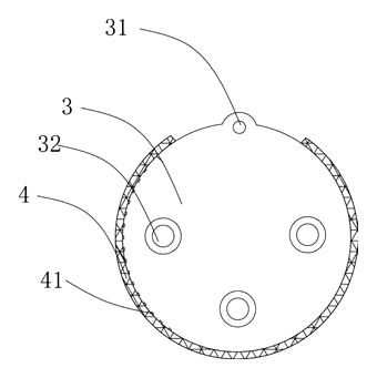
Drawings reproduced from the public patent document for reference.
Frequently asked questions
How does it separate the paper sheets?
It uses an air blowing device with multiple holes positioned between the top two sheets. By injecting a burst of air, it breaks the static cling and friction, allowing the vacuum suction cups to pick up only the top sheet.
Does it work with any toilet seat cover?
The patent specifies common water-soluble packing paper. The dimensions of the stack and the position of the suction cups must match the paper size. Custom holders can be designed for different paper formats.
What happens if the paper runs out?
Infrared altitude sensors monitor the height of the paper stack. When the level drops below a threshold, the system can alert the user or stop the cycle to prevent empty picks. The backing plate automatically raises to keep the top sheet at the correct pickup height.
Is the mechanism noisy?
The air blow and vacuum pump operations are brief. Noise levels depend on the choice of pump and enclosure design. Dampening materials can be added to the housing to meet quiet-operation targets for residential use.
Can it be installed on existing toilets?
It requires replacing the current lid with the specialized mechanism lid. The pivot and seat attachment must match the existing toilet geometry. Retrofit kits would need custom brackets for each toilet brand and model.
How is the paper held on the seat?
After the lid rotates and places the paper, the vacuum on the lid releases. The paper rests on the seat. Some designs may use additional vacuum holes in the seat area or rely on the paper’s natural adhesion to the dry surface.
Can this design be made and sold in the US?
The patent is filed in China and is in force there. The public record shows no US counterpart, so this specific Chinese patent does not restrict production or sales in the US. However, other US patents may cover similar automated dispenser technologies. We recommend a freedom-to-operate review before launching.
Are you affiliated with the patent owner?
No. IP2M is an independent design and manufacturing service working from the public patent document.
Request a quote
Click Request a Quote below to see our email address - copy it, or open your email app with a ready-made message. Please mention patent CN108685518B in the subject.
Helpful details to include:
- Your company and channel (sanitary ware manufacturer, hotel supplier, smart home integrator)
- Target toilet models and lid dimensions
- Paper specifications (size, material, roll or stack format)
- Power requirements (battery, AC adapter, wired)
- Estimated quantity and target price
- Timeline - when you would like samples and the first shipment
You can also reach us at (332) 203-9997.
Page editor: Emily Zhang, Product Editor · IP2M
Last updated November 8, 2026. If something on this page looks wrong, email [email protected] and we will check it against the patent.
Interested in building this?
Tell us your target market, quantity and timeline. We reply with options for prototyping, small-batch runs or volume production.
Send your inquiry to
Please put CN108685518B in the subject line and tell us your company, country, estimated quantity and timeline.
Prefer to talk? Call (332) 203-9997.
More product-ready patents
All Bath & Personal Care patents →
Bath & Personal Care
Foot-Pedal Soap & Sanitizer Dispenser Stand
Hands-free, battery-free dispenser stand - step on a pedal to press the pump of any soap or sanitizer bottle.
Patent CN207461995U
Bath & Personal Care
Ear-Shaped Mask Strap Guard with Tension Adjuster
Ear-shaped silicone guard and strap-length adjuster that make ear-loop masks comfortable to wear for long hours.
Patent CN205456233U
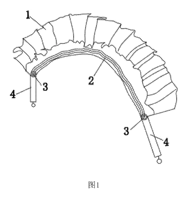
Bath & Personal Care
Adjustable-Length Back Scrubber Strap with Push-Button Handles
Back-scrubber strap with push-button handles that set its length and a spring that keeps it taut.
Patent CN207041452U
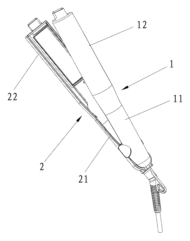
Bath & Personal Care
Angled-Plate Hair Straightener
Flat iron with plates twisted 45-75° to the handle, a curling groove and rubber-capped tips.
Patent CN206137462U
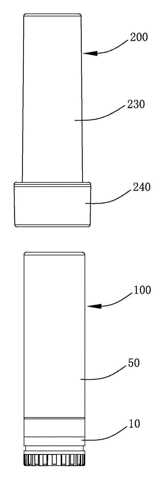
Bath & Personal Care
Refillable Lipstick Case with Sealed Snap-In Refill Pods
Reusable twist-up lipstick case; sealed refill pods unlock at the top of the stroke for shade swaps.
Patent CN206909979U
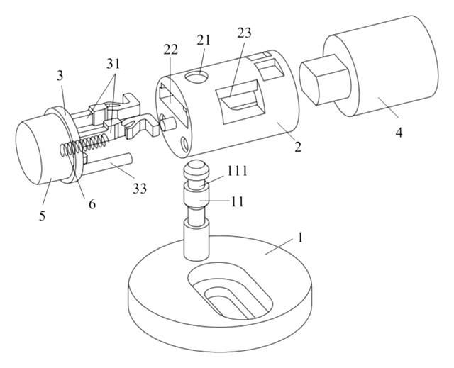
Bath & Personal Care
Quick-Release Toilet Seat Hinge with a Push-Button Two-Strip Latch
Toilet seat hinge: drop the shaft onto a grooved post to lock; one push parks the latch open to lift it off.
Patent CN210370292U
Browse by category
- Apparel & Accessories (52)
- Baby & Kids (31)
- Bags & Luggage (18)
- Bath & Personal Care (34)
- Car Accessories (27)
- Furniture, Bedding & Storage (26)
- Garden & Outdoor (34)
- Health & Wellness (15)
- Home, Kitchen & Cleaning (53)
- Lighting (25)
- Packaging & Containers (13)
- Pet Products (12)
- Phone & Camera Accessories (11)
- Retail Display (27)
- School, Office & Art (39)
- Sports & Recreation (50)
- Tools & Workshop (58)
- Toys & Games (24)
This page is based on the public patent document CN108685518B, assigned to Ningbo Jingjie International Logistics Co ltd. IP2M is an independent manufacturing service and is not affiliated with, endorsed by or licensed by the patent owner. Images marked as concept renderings are illustrations, not photos of an existing product. Patent status information is provided for reference only and is not legal advice; confirm freedom to operate for your market before production. Full disclaimer.